Wet process desulphurization demisting device and wet process desulphurization device

A wet desulfurization and demisting device technology, applied in separation methods, chemical instruments and methods, vapor condensation, etc., can solve the problems of low capture capacity of fine droplets and solid particles, reduced demisting efficiency, scaling, etc. , to achieve good demisting effect, avoid gypsum rain, and not easy to scale and block.

Inactive Publication Date: 2016-04-13
YANTAI LONGYUAN POWER TECH
View PDF13 Cites 3 Cited by
  • Summary
  • Abstract
  • Description
  • Claims
  • Application Information

AI Technical Summary

Problems solved by technology

The currently used demisters have a low ability to capture fine liquid droplets and solid particles. At the same time,

Method used


Image

  • Wet process desulphurization demisting device and wet process desulphurization device
  • Wet process desulphurization demisting device and wet process desulphurization device
  • Wet process desulphurization demisting device and wet process desulphurization device

Examples


Example Embodiment

[0025] Example one:

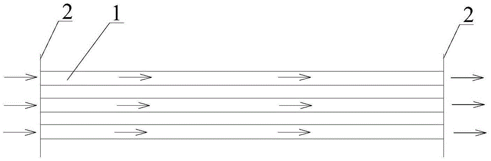
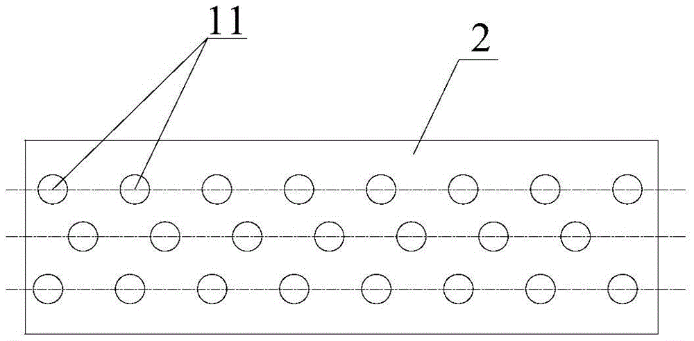
[0026] This embodiment provides a wet desulfurization and mist removal device, such as figure 1 with figure 2 As shown, it includes at least two layers of parallel tube rows 1, the two ends of the tube rows 1 are respectively supported on the support 2, and the two adjacent layers of tube rows 1 are staggered, and each layer of tube rows 1 includes multiple The hollow thin tubes 11 parallel to each other also include a cooling medium source (not shown in the figure). At least part of the hollow thin tubes 11 are in communication with a cooling medium source. The cooling medium source is used to provide a cooling medium for the hollow thin tubes 11 to cool the hollow thin tubes. 11. The cooling medium in the cooling medium source is preferably cooling water, which is non-toxic, low in cost, and has a good cooling effect, but the cooling medium is not limited to water, and can also be some other non-toxic medium with cooling effect. The structure and shape o...

Example Embodiment

[0034] Embodiment two:

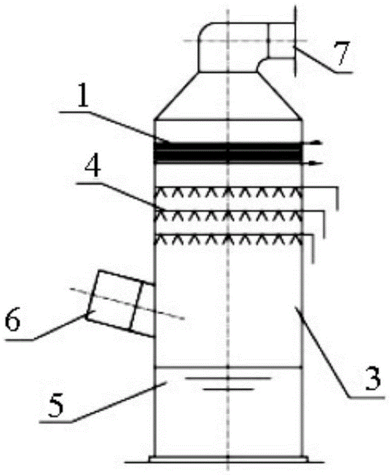
[0035] This embodiment provides a wet desulfurization device including the wet desulfurization and mist removal device described in the first embodiment, such as image 3 As shown, it includes a wet desulfurization tower 3, and a wet desulfurization and mist removal device is placed above the spray layer 4 of the wet desulfurization tower.

[0036] More specifically, the bottom of the wet desulfurization tower is provided with a slurry tank 5, the side wall of the desulfurization tower 3 is provided with a desulfurization tower inlet 6, the top of the desulfurization tower 3 is provided with a desulfurization tower outlet 7, and the desulfurization tower 3 is provided with the above-mentioned spray The spray layer 4, the wet desulfurization and mist removal device is placed above the spray layer 4 of the wet desulfurization tower. The flue gas first enters the desulfurization tower through the inlet of the desulfurization tower, and then passes through the...


PUM


Abstract

The invention discloses a wet process desulphurization demisting device and a wet process desulphurization device, and belongs to the technical field of wet process desulphurization. The wet process desulphurization demisting device provided by the invention comprises at least two layers of parallel pipe rows; the two adjacent layers of pipe rows are in staggered arrangement; each layer of pipe row respectively comprises a plurality of mutually parallel hollow thin pipes and also comprises a cooling medium source; at least partial hollow thin pipes are communicated with the cooling medium source; the cooling medium source is used for providing cooling media for the hollow thin pipes. According to the wet process desulphurization demisting device and the wet process desulphurization device provided by the invention, the cooling media are communicated inside the pipe rows for cooling smoke gas; water vapor in the smoke gas can be condensed by using fine particulate matters and liquid drops as the core, so that the mass of the fine particulate matters and the liquid drops can be increased; the inertia is increased; the catching capability of the demisting device on the fine particulate matters and the liquid drops is improved; the generation of gypsum rain is avoided; the demisting effect is improved. The wet process desulphurization device provided by the invention is provided with the wet process desulphurization demisting device, and has the advantages that the scale formation blockage cannot easily occur; the demisting effect is good.

Description

technical field [0001] The invention relates to the technical field of wet desulfurization, in particular to a wet desulfurization and demisting device and a wet desulfurization device provided with the wet desulfurization and demisting device. Background technique [0002] At present, the wet desulfurization system of coal-fired boilers is prone to generate mist droplets mixed with gypsum during operation, which needs to be captured by demisters. Wet desulfurization generally uses ridge-type demisters and tube-type demisters. The principle is Relying on the inertia and gravity of the slurry droplets in the flue gas, the flue gas is forced to change direction continuously during the movement, so that the flue gas flow can achieve gas-liquid separation under the action of inertial force and centrifugal force, and achieve the purpose of demisting. The currently used mist eliminators have a low ability to capture fine liquid droplets and solid particles. At the same time, with ...

Claims


Application Information

Patent Timeline
IPC IPC(8): B01D5/00B01D53/80B01D53/50
CPCB01D5/0009B01D53/002B01D53/504B01D53/80
Inventor 蒋海涛李斌付玉玲贾明华张玉斌
Owner YANTAI LONGYUAN POWER TECH
Why Eureka
Try Eureka