
Dust-removing conveying mechanism for fodder

A transmission mechanism and feed technology, applied in the direction of conveyor objects, transportation and packaging, cleaning devices, etc., can solve the problems of raw material pollution, material waste, dust flying, etc., to achieve the effect of removing pollution and ensuring purity

Inactive Publication Date: 2016-04-13
天津禾普饲料有限公司
View PDF1 Cites 0 Cited by
  • Summary
  • Abstract
  • Description
  • Claims
  • Application Information

AI Technical Summary

Problems solved by technology

[0002] The feed transmission mechanism is an essential production equipment for feed production enterprises. It is used for the transmission of feed raw materials, and is generally used for short-distance transportation between feed production equipment. Its main component is the screw, which can transport raw materials smoothly through the movement of the screw. ; Feed in the prior art is likely to cause dust to fly and waste materials; Chinese patent application number: 201220525621.8 discloses a screw conveyor, including a conveyor shell and a screw shaft set in the middle of the conveyor shell, and the conveyor shell is horizontal The placed cylindrical structure has a feed inlet on the upper right side of the conveyor shell, and a discharge port on the lower left side of the conveyor shell; the screw blade is installed on the screw shaft, and the right end of the screw shaft is connected with the reducer and the motor in sequence The left and right ends and the middle of the conveyor shell are equipped with bearing support seats, and the screw shaft is installed on the bearing support seats; the invention has good sealing performance, and the problems of dust flying, material waste and environmental pollution will not occur when transporting materials , and the structure is simple and easy to operate; but because this kind of conveyor seals the dust in the raw material of the shell, it is easy to cause raw material pollution, resulting in unqualified feed products

Method used


Image

  • Dust-removing conveying mechanism for fodder

Examples


Embodiment 1

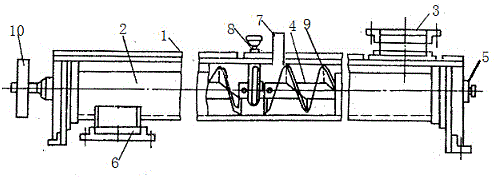
[0014] Such as figure 1 As shown, a feed dust removal transmission mechanism of the present invention includes a body 1; a through groove 2 is provided inside the body 1; a feed port 3 is provided at one end of the body 1; a transmission port 3 is provided below the feed port 3 Device 4; a transmission mechanism 5 is provided behind the transmission device 4, and a power mechanism 10 is provided on its front side; a discharge port 6 is provided under the front side of the transmission device 4; a body 1 on the upper side of the transmission device is provided with There is a dust removal pipe 7; the dust removal pipe 7 is installed in cooperation with a suction device (not shown).

[0015] Wherein, the transmission device 4 is composed of a screw shaft 9; the rear end of the screw shaft 9 is installed in cooperation with the bearing, and its front side is installed in cooperation with the power mechanism 10; the dust removal pipe 7 is installed in cooperation with the air suc...


PUM


Abstract

The invention discloses a dust-removing conveying mechanism for fodder. The dust-removing conveying mechanism comprises a machine body; a through groove is formed in the inner side of the machine body; a feed port is formed in one end of the machine body; a conveying device is arranged below the feed port; a transmission mechanism is arranged behind the conveying device, and a power mechanism is arranged in front of the conveying device; a discharge port is formed below the front side of the conveying device; a dust-removing pipe is arranged at the part, at the upper side of the conveying device, of the machine body; the dust-removing pipe and an air induction device are installed in a matched mode. According to the invention, pollution to the inner side of the conveying mechanism can be effectively removed, and waste of raw material can be avoided; the dust-removing pipe is arranged in the middle of the machine body and is higher than the top surface of the machine body, and therefore the raw material can be prevented from leaking; meanwhile, the dust-removing pipe sucks out the part, with dust, of the raw material, and therefore the purity of the raw material can be guaranteed.

Description

technical field [0001] The invention belongs to the technical field of feed production equipment, and in particular relates to a feed dust removal transmission mechanism. Background technique [0002] The feed transmission mechanism is an essential production equipment for feed production enterprises. It is used for the transmission of raw materials for feed, and is generally used for short-distance transportation between feed production equipment. Its main component is the screw, which can transport raw materials smoothly through the movement of the screw. ; Feed in the prior art is likely to cause dust to fly and waste materials; Chinese patent application number: 201220525621.8 discloses a screw conveyor, including a conveyor shell and a screw shaft set in the middle of the conveyor shell, and the conveyor shell is horizontal The placed cylindrical structure has a feed inlet on the upper right side of the conveyor shell, and a discharge port on the lower left side of the ...

Claims


Application Information

Patent Timeline
IPC IPC(8): B65G45/10
Inventor 李雅松王文红
Owner 天津禾普饲料有限公司
Learn More