

A structure and construction method for strengthening the connection between precast concrete segments
A technology of precast concrete and construction method, applied in bridge parts, erection/assembly of bridges, bridge materials, etc., can solve problems such as vehicle falling bridges, fractures, etc., to improve bearing capacity and durability, good overall performance, and low technical requirements Effect
- Summary
- Abstract
- Description
- Claims
- Application Information
AI Technical Summary
Problems solved by technology
Method used
Image

Examples
Embodiment 1
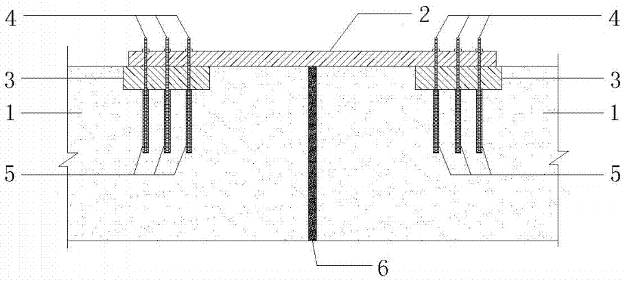
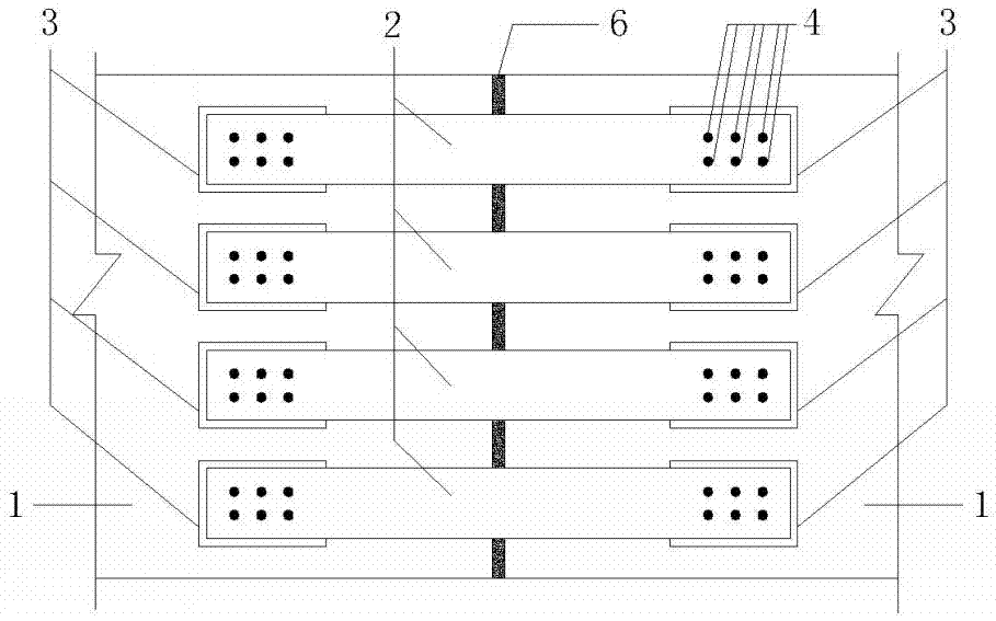
[0032] The schematic diagram corresponding to this embodiment is shown in figure 1 and image 3 , there is an embedded steel plate (3) on the upper surface of the bottom plate (1) of the prefabricated segment, the distance from the edge of the embedded steel plate (3) to the seam (6) is 20cm, and the thickness of the embedded steel plate (3) is 20mm, the lower surface of the pre-embedded steel plate (3) is welded with a sleeve (5) with internal threads, and holes corresponding to the internal threads of the sleeve (5) are made on the pre-embedded steel plate (3), connecting the steel plate (2) The thickness is 16mm, the connecting steel plate (2) crosses the seam (6), connects with the embedded steel plate (3) through the screw rod (4), the screw rod (4) is screwed into the sleeve (5), and reaches the sleeve (5 ), the main girder is arranged in 4 rows of connecting steel plates (2) along the direction of the bridge, there are screw rods (4) at the ends of the connecting steel...
Embodiment 2
[0038] For the schematic diagram corresponding to this embodiment, see Figure 5 , the difference between this embodiment and the first embodiment is that: the added structure is arranged on the lower surface of the bottom plate (1) of the prefabricated segment, the structure of this embodiment can effectively avoid or delay the cracking of the seam (6), The bending resistance of the main girder can be improved more effectively, and the construction method is similar to that of the first embodiment.
Embodiment 3
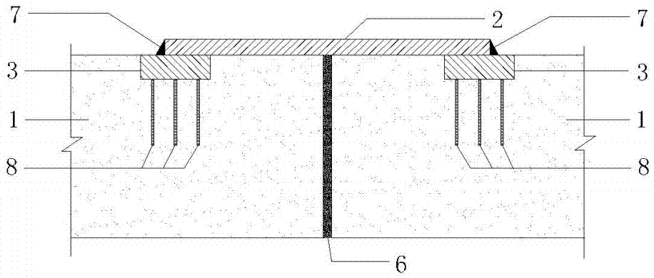
[0040] For the schematic diagram corresponding to this embodiment, see figure 2 and Figure 4 , the difference between this embodiment and the first embodiment is that the embedded steel plate (3) on both sides of the joint (6) is connected with the connecting steel plate (2) through the weld (7), and the weld (7) is three sides Surrounding welding, anchoring steel bar (8) is welded under the pre-embedded steel plate (3), the length of the anchoring steel bar (8) is 25cm, and the main beam is arranged in 4 rows of connecting steel plates (2) along the transverse direction of the bridge, and it is symmetrical along the transverse direction of the main beam The distribution and construction method are similar to those in Example 1, and the bolted connection is changed to site welding, which avoids the difficulty in installing the screw (4) that may be caused by the error in the position of the opening on the connecting steel plate (2). Because it is downward welding, the opera...
PUM
 Abstract
Description
Claims
Application Information