
Tooth implantation drilling robot based on small cavity

A robot, small cavity technology, applied in surgical robots, dental implants, dentistry, etc., can solve the problems of reduced flexibility of drilling robots, difficult access of robotic hands to drilling operations, and no degree of freedom of drilling actuators. , to avoid additional damage, compact structure, and improve flexibility

Inactive Publication Date: 2016-04-20
HEBEI UNIV OF TECH
View PDF6 Cites 14 Cited by
  • Summary
  • Abstract
  • Description
  • Claims
  • Application Information

AI Technical Summary

Problems solved by technology

The image-guided dental implant robot researched by Old Dominion University in the United States is a relatively advanced set of robots so far, but it has not been used in clinical practice, and it is still in the experimental stage in general. Except for the rotation of the drill bit, the drilling actuator itself No degree of freedom, can not do bending movement, which limits the flexibility of the whole robot
On the one hand, the cavity space of the human oral cavity is small, and the structure varies from person to person. Some positions are difficult for the robot to reach and perform drilling operations. Moreover, the reduced flexibility of the drilling robot will limit its application in other surgical operations
On the other hand, in the real oral surgery, the field of view of the implant robot will be blocked due to the lack of flexibility at the end, which will make the operation more difficult and affect the quality of the operation

Method used


Image

  • Tooth implantation drilling robot based on small cavity
  • Tooth implantation drilling robot based on small cavity
  • Tooth implantation drilling robot based on small cavity

Examples


Embodiment Construction

[0017] The present invention will be further explained in detail below in conjunction with the embodiments and the drawings, but it is not used as a limitation to the protection scope of the claims of this application.

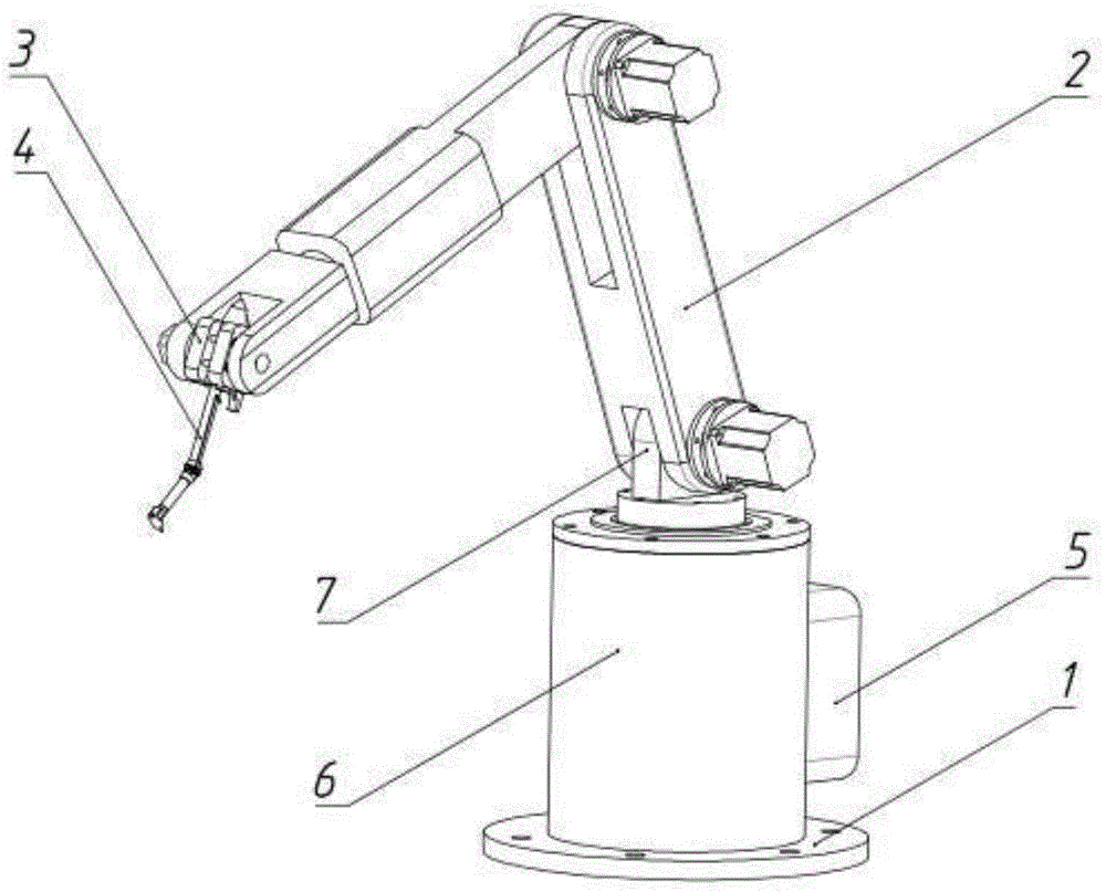
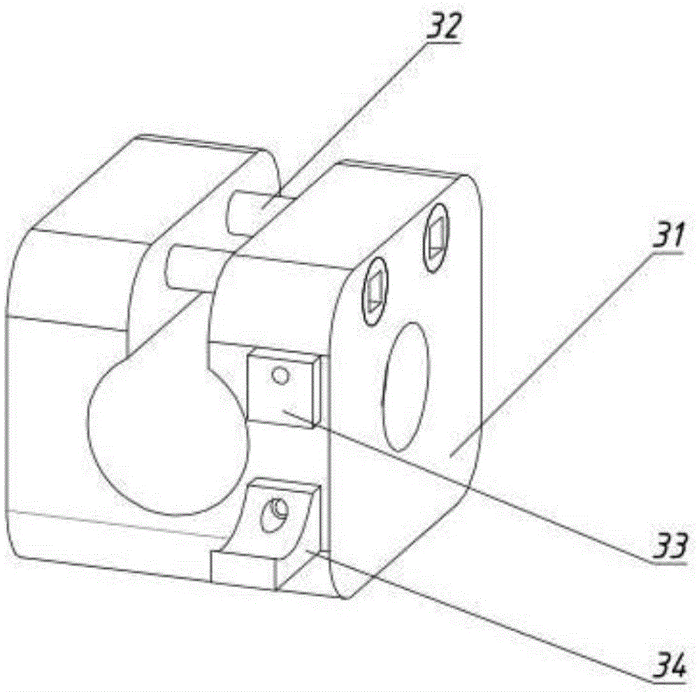
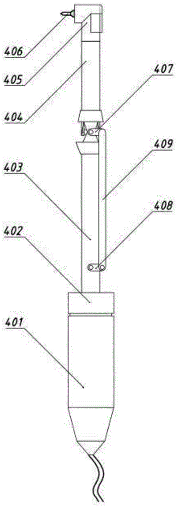
[0018] The present invention is a dental implant drilling robot based on a small cavity (referred to as robot, see Figure 1-5 ) Including the carrying chassis 1, the mechanical arm 2, the clamp 3, the drilling actuator 4, the control box 5, the chassis turbine box 6 and the driving arm seat 7. The lower part of the chassis turbine box 6 is fixed on the carrying chassis 1, and the upper part is connected with the driving arm seat 7 is connected, the upper part of the driving arm base 7 is provided with a connecting hole; the control box 5 is connected to an external computer through a wire, and is fixed on the chassis turbine box 6 at the same time, and one end of the mechanical arm 2 is connected to the connecting hole on the driving arm base 7 , The other end is...


PUM


Abstract

The invention relates to a tooth implantation drilling robot based on a small cavity. The robot comprises a bearing chassis, a mechanical arm, a clamp, a drilling executor, a control box, a chassis turbine box and a driving arm base. The lower portion of the chassis turbine box is fixed to the bearing chassis. The upper portion of the chassis turbine box is connected with the driving arm base. The upper portion of the driving arm base is provided with a connection hole. The control box is connected with an external computer through a wire and meanwhile fixed to the chassis turbine box. One end of the mechanical arm is connected with the connection hole in the driving arm base. The other end of the mechanical arm is connected with one end of the clamp. The other end of the clamp is connected with the drilling executor. The tooth implantation drilling robot is characterized in that the drilling executor comprises a medical special brushless motor, a speed reducer, a rear axle housing, a front axle housing, a machine head shell, a drill bit, a small connecting rod, a crank, a large connecting rod, a rear transmission shaft, a front transmission shaft, a bevel gear, a one-piece gear spindle and a universal joint pin. The medical special brushless motor is connected with one end of the rear transmission shaft through the speed reducer, and the other end of the rear transmission shaft is connected with one end of the front transmission shaft through the universal joint pin.

Description

Technical field [0001] The invention relates to the technical field of drilling machinery for medical and surgical operations, in particular to a dental implant drilling robot based on a small cavity. Background technique [0002] At present, the prevalence of dental and jaw deformity in my country exceeds 60%. Fixation device technology is the most common and effective method of tooth restoration and correction. However, tooth damage caused by trauma requires tooth implantation. Robotic tooth implantation is a robot technology. A brand new application in the medical field. [0003] Implant dentures are implants (artificial tooth roots) placed in the alveolar bone of the oral cavity. After a few months, the osseointegration is completed, and then the artificial tooth root is installed with the denture. [0004] In the process of tooth implantation, it is very important to implant the artificial tooth root in the ideal position. In addition, the quality of the drilling directly determ...

Claims


Application Information

Patent Timeline
IPC IPC(8): A61C8/02A61B34/30
CPCA61C8/0089
Inventor 张顺心王晓东韩立贾少薇武晓丹尹立轶
Owner HEBEI UNIV OF TECH
Learn More