In-situ heat treatment method for realizing electron beam selective melting material increase manufacturing of metal parts

A technology of additive manufacturing and selective melting, which is applied in the directions of additive manufacturing, process efficiency improvement, and energy efficiency improvement. It can solve the problems of increasing production and manufacturing costs, and achieve the effect of improving surface finish and eliminating microscopic holes.

Active Publication Date: 2016-04-20
成都航大新材料有限公司
View PDF7 Cites 33 Cited by
  • Summary
  • Abstract
  • Description
  • Claims
  • Application Information

AI Technical Summary

Problems solved by technology

But HIP processing will lead t

Method used


Image

  • In-situ heat treatment method for realizing electron beam selective melting material increase manufacturing of metal parts
  • In-situ heat treatment method for realizing electron beam selective melting material increase manufacturing of metal parts
  • In-situ heat treatment method for realizing electron beam selective melting material increase manufacturing of metal parts

Examples


Embodiment 1

[0026] Example 1: In-situ heat treatment of TC4 alloy

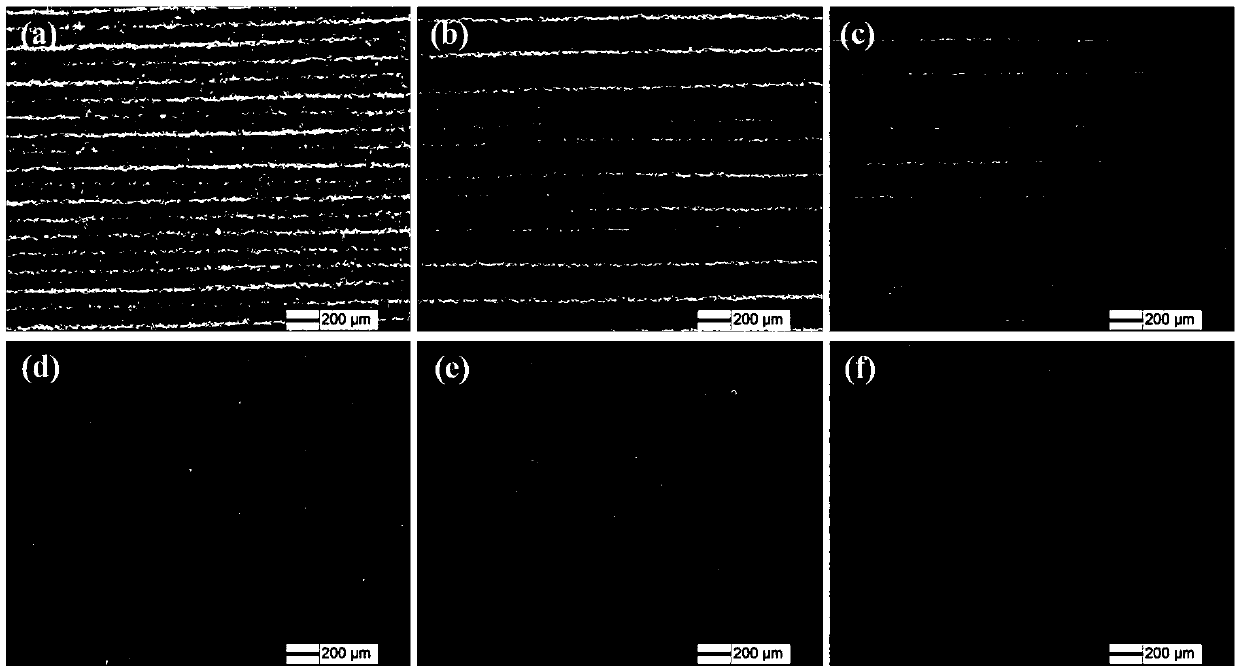
[0027] EBM equipment is used to process six TC4 alloy test blocks at the same time, and the size is 20mm×20mm×80mm. One of the test blocks was processed by the normal process, the electron beam current was 4.5mA, the scanning speed was 700m / s, the FocusOffset value was 3, and no secondary remelting in-situ heat treatment was performed. For the remaining 5 test blocks, the electron beam FocusOffset values ​​were set to 3, 10, 20, 40, and 60 for in-situ remelting treatment, and the electron beam current and scanning speed were not changed during the remelting process. figure 2 It is the surface morphology of TC4 alloy treated with different processing parameters. From figure 2 In (a), it can be seen that there are obvious electron beam scanning traces on the surface of the unremelted sample. After the second remelting treatment, the surface state of the sample changes, and the sample surface obtained when the FocusOffs...

Embodiment 2

[0031] Example 2: In-situ heat treatment of Inconel625 alloy

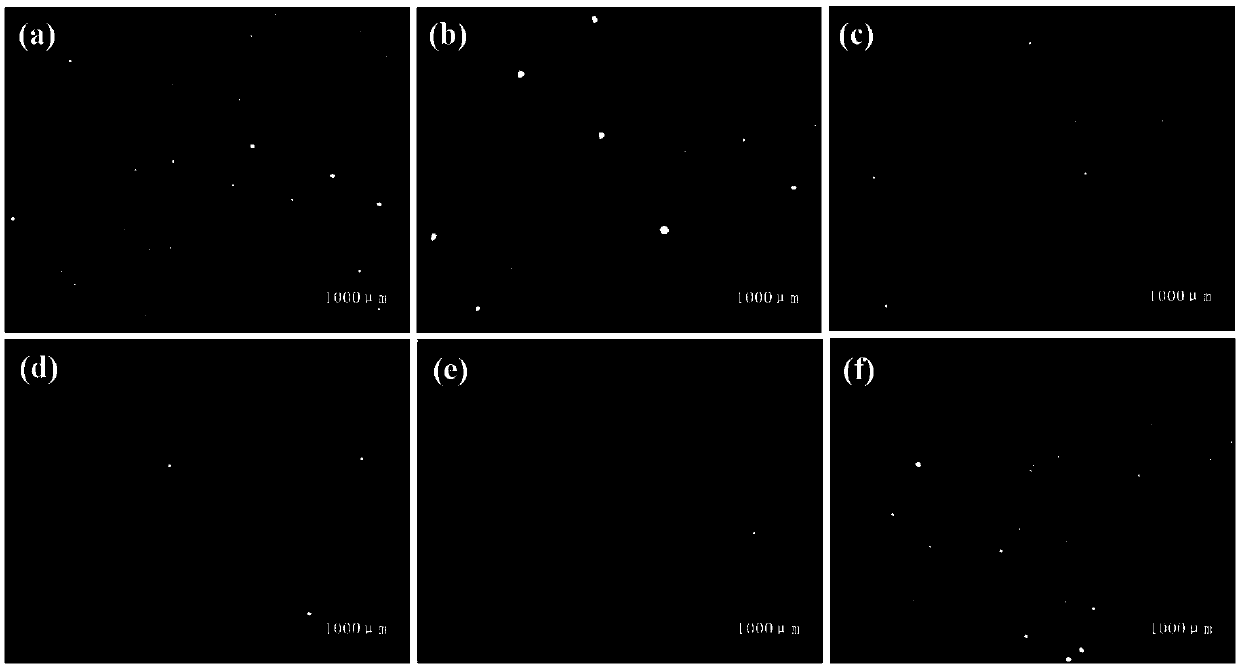
[0032] EBM equipment is used to process 4 pieces of Inconel625 alloy test blocks at the same time, and the sizes are all One of them (denoted as 1# test block) was processed by normal process, the processing electron beam current was 4.5mA, the scanning speed was 500m / s, the FocusOffset value was 20, and no secondary remelting in-situ heat treatment was performed. The parameters of the in-situ heat treatment for the other two test blocks are respectively: the electron beam current is 4.5mA, the scanning speed is 1000m / s, and the FocusOffset value is 20 (denoted as 2# test block); the electron beam current is 4.5mA, and the scanning speed is 400m / s, FocusOffset value is 40 (recorded as 3# test block). Figure 6 The cross-sectional metallographic pictures and Figure 7 The electron backscatter diffraction (EBSD) images are the microscopic analysis results of the Inconel625 alloy before and after the remelting tre...


PUM

PropertyMeasurementUnit
Tensile strengthaaaaaaaaaa
Tensile strength at room temperatureaaaaaaaaaa

Abstract

The invention discloses an in-situ heat treatment method for realizing electron beam selective melting material increase manufacturing of metal parts, relating to the technical field of material increase manufacturing and heat treatment. The method adds a step of secondary heating remelting to melt a forming zone after a step of forming zone melting. The secondary heating remelting parameters comprise the electron beam current scanning speed, the electron beam current, the scanning deflection amount and the focal spot size. The method carries out in-situ heat treatment in the process of part processing forming process, therefore eliminates part of micro holes in the parts, and meanwhile can improve the surface smoothness of the parts, realize micro-structure controlling and realize regulation and control for the mechanical property of forming parts in a certain range.

Description

technical field [0001] The invention relates to a method for in-situ heat treatment of additively manufactured metal parts, in particular to a method for in-situ heat treatment of electron beam selective melting and additively manufactured metal parts. By performing in-situ heating or remelting heat treatment on metal parts during the forming process, some microscopic holes can be eliminated, the surface finish of the parts can be improved, and the microstructure can be adjusted, so as to realize the regulation of the mechanical properties of the formed parts within a certain range. Background technique [0002] High-energy beam 3D printing technology is the main development direction of rapid prototyping of metal parts. The 3D printing technology developed in recent years using high-energy beams (electron beams, laser beams, plasma beams, etc.) as heat sources is the main development direction for rapid prototyping of metal parts, which can greatly improve the production ef...

Claims


Application Information

Patent Timeline
IPC IPC(8): B22F3/105B22F3/24
CPCB22F3/24B22F2003/248B22F10/00B22F10/364B22F10/28B22F10/366B22F10/362Y02P10/25
Inventor 彭徽郭洪波汤一彪宫声凯徐惠彬
Owner 成都航大新材料有限公司
Why Eureka
Try Eureka