Detection system for tool chattering in milling and detection method thereof

A milling processing and detection system technology, applied in the direction of manufacturing tools, metal processing equipment, metal processing machinery parts, etc., can solve the problems of difficulty in obtaining vibration signals, low efficiency, and influence of chatter signal analysis, etc.

Inactive Publication Date: 2016-04-20
NANJING INST OF TECH
View PDF10 Cites 15 Cited by
  • Summary
  • Abstract
  • Description
  • Claims
  • Application Information

AI Technical Summary

Problems solved by technology

[0004] In order to solve the deficiencies of the prior art, the purpose of the present invention is to provide a detection system and detection method for tool chatter in milling, which solves the difficulty and inefficiency in obtaining a large number of vibration signals in the current milling process. An issue where the analysis of flutter signals would also be affected by components not related to flutter

Method used


Image

  • Detection system for tool chattering in milling and detection method thereof
  • Detection system for tool chattering in milling and detection method thereof
  • Detection system for tool chattering in milling and detection method thereof

Examples


Embodiment Construction

[0037] The present invention will be further described below in conjunction with the drawings. The following embodiments are only used to illustrate the technical solutions of the present invention more clearly, and cannot be used to limit the protection scope of the present invention.

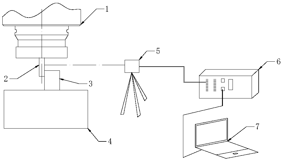
[0038] Such as figure 2 As shown, the detection system includes a displacement detection unit, a data acquisition unit, and a central processing unit. In this embodiment, a multi-point laser displacement sensor is arranged around the CNC machine tool. During the processing, the laser displacement sensor measures multiple points on the tool surface at each moment.

[0039] The multi-point laser displacement sensor is connected to the central processing unit through a USB data transmission line, and the displacement signal detected by the sensor is transmitted to the central processing unit to collect the corresponding data signal.

[0040] The displacement signal is expressed as: X = [ ...


PUM


Abstract

The invention discloses a detection system for tool chattering in milling and a detection method thereof, characterized by comprising following steps: 1), selecting a suitable displacement sampling window; 2), determining a center of a tool and vibration changes corresponding to the center of the tool by using a radius constrained least square method; 3), subjecting a tool vibration signal to empirical mode decomposition, and obtaining a time-frequency spectrum using HHT (Hilbert Huang transform); 4), verifying whether the time-frequency spectrum meets chattering rule. The invention has the advantages that the use of a non-contact detection method, using a laser displacement sensor, overcomes limitations such as size of a workpiece under processing, mass, a mounting mode, and high precision is provided; by studying the influence of milling chattering and tool eccentricity upon positional changes of the center of the tool, positional flutter of the center of circle of the tool is determined, and thus chattering change conditions of the tool are directly reflected; by using Hilbert Huang transform, the limitations of Fourier transform can be overcome and a time-frequency spectrum of signals can be better described.

Description

Technical field [0001] The invention relates to a detection system and a detection method for tool chatter in milling processing, and belongs to the technical field of processing detection. Background technique [0002] High-speed milling processing has outstanding advantages such as high production efficiency, high surface quality, low manufacturing cost and short product development cycle. It is widely used in aviation, aerospace, mold, automotive and other manufacturing industries to meet the continuous development of manufacturing needs. However, the many advantages of high-speed milling must be premised on the vibration-free and stable milling process at high speeds. During the milling process, due to the milling force and other uncertain loads, the process system tends to chatter. The occurrence of milling chatter will not only reduce the quality of the machined surface of the workpiece, but also affect the service life of the tool and even the lathe. In "Made in China 20...

Claims


Application Information

Patent Timeline
Patent Type & Authority Applications(China)
IPC IPC(8): B23Q17/09B23Q17/12
CPCB23Q17/09B23Q17/12
Inventor 王保升张蒙蒙左健民汪木兰候军明
Owner NANJING INST OF TECH
Why Eureka
Try Eureka