Laminated glass capable of emitting light
A technology of laminated glass and inner glass, applied in windshield, glass/slag layered products, layered products, etc., can solve the problems of no sense of layering, no obvious directionality of output light, etc., and achieve a simple and compact structure Effect
- Summary
- Abstract
- Description
- Claims
- Application Information
AI Technical Summary
Problems solved by technology
Method used
Image
Examples
Embodiment 1
[0049] 1) The thickness is 2.1mm, and the length and width are 300×300mm 2 The gray transparent glass plate is used as the inner glass 2, with a thickness of 2.1mm and a length and width of 300×300mm 2 The white transparent glass plate is used as the outer glass 1.
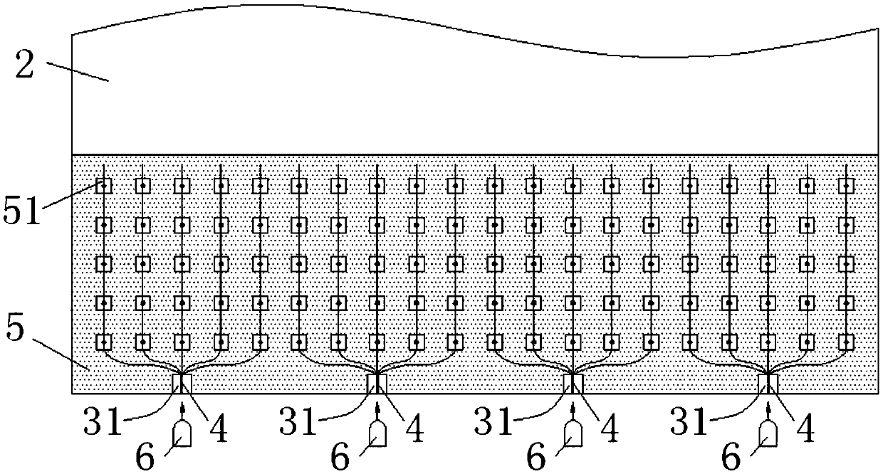
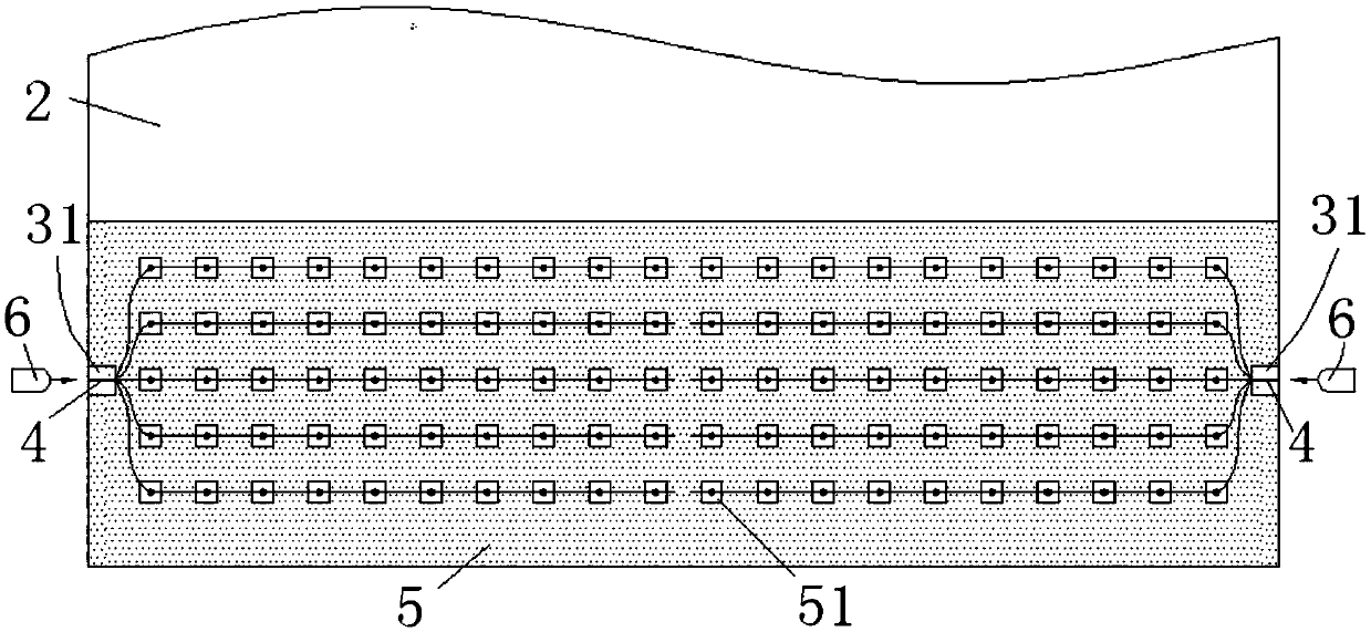
[0050] 2) Take a piece with a thickness of 0.38mm and a length and width of 300×300mm 2 The transparent PVB film (refractive index 1.49), with the aid of tools such as templates, the optical fiber bundle 4 that is split and provided with a cutting part is laid on the transparent PVB film (refractive index 1.49) according to a certain pattern, and the optical fiber bundle is kept The head end of 4 is aligned with the edge of PVB film.
[0051] 3) Another transparent PVB film (refractive index: 1.49) of the same size is covered on the optical fiber bundle 4, and the two PVB films above and below the optical fiber bundle 4 are completely overlapped. Each optical fiber bundle 4 includes 25 optical fiber cores, the ...
Embodiment 2
[0056] 1) The thickness is 2.1mm, and the length and width are 300×300mm 2 The green transparent glass plate is used as the inner glass 2, with a thickness of 2.1mm and a length and width of 300×300mm 2 The white transparent glass plate is used as the outer glass 1.
[0057] 2) Take a piece with a thickness of 0.38mm and a length and width of 300×300mm 2The transparent PVB film (refractive index 1.49), with the aid of tools such as templates, the optical fiber bundles 4 that are split and provided with corroded parts are arranged on the transparent PVB film (refractive index 1.49) according to a certain pattern, and the optical fiber bundles are kept The head end of 4 is aligned with the edge of PVB film.
[0058] 3) Another transparent PVB film (refractive index: 1.49) of the same size is covered on the optical fiber bundle 4, and the two PVB films above and below the optical fiber bundle 4 are completely overlapped. Each optical fiber bundle 4 includes 15 optical fiber co...
Embodiment 3
[0063] 1) The thickness is 2.1mm, and the length and width are 300×300mm 2 The green transparent glass plate is used as the inner glass 2, with a thickness of 2.1mm and a length and width of 300×300mm 2 The white transparent glass plate is used as the outer glass 1.
[0064] 2) Take a piece with a thickness of 0.38mm and a length and width of 300×300mm 2 transparent PVB film (refractive index 1.49), with the aid of tools such as templates, the split optical fiber bundle 4 is arranged on the transparent PVB film (refractive index 1.49) according to a certain pattern, and the head end of the optical fiber bundle 4 is kept in contact with the PVB film edges are aligned.
[0065] 3) Another transparent PVB film (refractive index: 1.49) of the same size is covered on the optical fiber bundle 4, and the two PVB films above and below the optical fiber bundle 4 are completely overlapped. Each optical fiber bundle 4 includes 20 optical fiber cores, the diameter of the optical fiber ...
PUM
| Property | Measurement | Unit |
|---|---|---|
| Diameter | aaaaa | aaaaa |
| Diameter | aaaaa | aaaaa |
| Diameter | aaaaa | aaaaa |
Abstract
Description
Claims
Application Information
 - R&D
- Intellectual Property
- Life Sciences
- Materials
- Tech Scout
- Unparalleled Data Quality
- Higher Quality Content
- 60% Fewer Hallucinations
Browse by: Latest US Patents, China's latest patents, Technical Efficacy Thesaurus, Application Domain, Technology Topic, Popular Technical Reports.
© 2025 PatSnap. All rights reserved.Legal|Privacy policy|Modern Slavery Act Transparency Statement|Sitemap|About US| Contact US: help@patsnap.com


