
A new energy vehicle and two power control methods thereof

A new energy vehicle and vehicle controller technology, which is applied in the field of vehicle safety, can solve problems such as high safety risks, and achieve the effects of ensuring driving safety, reducing the risk of accidental acceleration, and safe control methods

Active Publication Date: 2017-11-14
ZHENGZHOU YUTONG BUS CO LTD
View PDF1 Cites 0 Cited by
  • Summary
  • Abstract
  • Description
  • Claims
  • Application Information

AI Technical Summary

Problems solved by technology

[0004] The purpose of the present invention is to provide a new energy vehicle to solve the problem of high safety risk when the traditional vehicle power system is controlled

Method used


Image

  • A new energy vehicle and two power control methods thereof
  • A new energy vehicle and two power control methods thereof
  • A new energy vehicle and two power control methods thereof

Examples


Embodiment 2

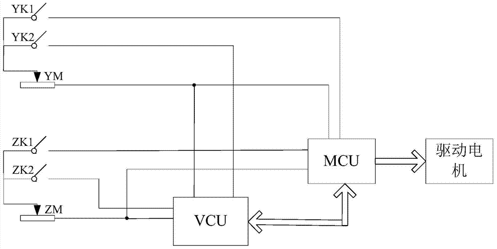
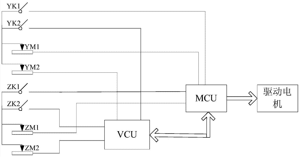
[0060] Such as Figure 5 A new energy vehicle shown includes an accelerator pedal, a brake pedal, a vehicle controller VCU, and a motor controller MCU. Both the vehicle controller and the motor controller are provided with brake control signal input ends, and the brake pedal is provided with a brake signal generating device. The accelerator signal generating device provided at the accelerator pedal is only connected to the accelerator control signal input terminal of the vehicle controller. Since the acquisition of the accelerator pedal signal is not the focus of this embodiment, it will not be described here. The vehicle controller and the motor controller are connected through the CAN bus.

[0061] The brake signal generating device includes two brake action switch elements ZK1, ZK2 and a brake force detection element ZM. The brake switch signals generated by the two brake action switch elements correspond to the brake switch signals on the vehicle controller and the motor ...

Embodiment 3

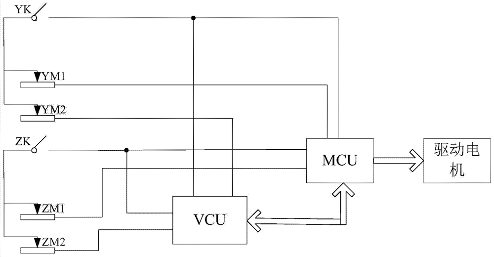
[0073] Such as Figure 9 A new energy vehicle shown includes an accelerator pedal, a brake pedal, a vehicle controller VCU, and a motor controller MCU. Both the vehicle controller and the motor controller are provided with accelerator control signal input ends, and the accelerator pedal is provided with an accelerator signal generating device. The brake signal generating device provided at the brake pedal is only connected to the brake control signal input terminal of the vehicle controller. Since the signal acquisition of the brake pedal is not the focus of this embodiment, it will not be described here. The vehicle controller and the motor controller are connected through the CAN bus.

[0074] The accelerator signal generating device includes two accelerator action switch elements YK1, YK2 and an accelerator opening detection element YM. The accelerator switch signals generated by the two accelerator action switch elements correspond to the accelerator signal input on the v...


PUM


Abstract

The invention relates to a new energy automobile and two kinds of power control methods. The new energy automobile comprises a pedal, a vehicle control unit and a motor controller, wherein a control signal input end of the vehicle control unit is connected with a signal generation device which is arranged on the pedal, the vehicle control unit is connected with the motor controller by a bus, and a control signal input end of the motor controller is connected with the signal generation device. In the two kinds of control methods, one method is that the motor controller judges whether a vehicle brakes or not according to the rationality of a brake signal, if the motor controller confirms the rationality of the brake signal, and no matter whether the received signal is the brake control signal or not, the motor controller performs brake control on the vehicle; the other method is that the motor controller needs not only throttle information of an accelerator pedal but also the drive command of the vehicle control unit, only when the two signals are provided simultaneously can a motor be driven to rotate, the risk of accident acceleration of the vehicle can be effectively reduced by the aid of double insurance, and vehicle driving safety is guaranteed.

Description

technical field [0001] The invention relates to a new energy vehicle and two power control methods thereof, belonging to the technical field of vehicle safety. Background technique [0002] As we all know, car safety is very important, especially in the current situation of increasingly complex automotive electronic systems, car safety-related systems may bring risks including unexpected acceleration, unexpected deceleration, and unexpected steering of the vehicle. The Automotive Safety Integrity Level (ASIL) is proposed in the functional safety standard ISO26262 "Road Vehicle Electrical and Electronic System Functional Safety Standard". In this safety standard, functional safety issues are divided into four levels: A, B, C, D. Where D represents the highest grade and A represents the lowest grade. The higher the safety integrity level, the higher the safety measures required. At the same time, the problem can be decomposed to reduce the risk, that is, an ASIL-C safety pro...

Claims


Application Information

Patent Timeline
Patent Type & Authority Patents(China)
IPC IPC(8): B60L15/28
CPCB60L15/20B60L15/2009B60L15/28Y02T10/72
Inventor 李钰锐彭能岭李振山王永秋张永强
Owner ZHENGZHOU YUTONG BUS CO LTD
Learn More