Catheter feeding device in medical assembling machine
A technology of feeding device and assembly machine, applied in the direction of conveyor, loading/unloading, mechanical conveyor, etc., can solve the problems of prolonged waiting time of medical assembly machine, fixed material box in place, low replacement efficiency, etc., to improve supply Material stability, fast and stable replacement, and the effect of improving stability
- Summary
- Abstract
- Description
- Claims
- Application Information
AI Technical Summary
Problems solved by technology
Method used
Image
Examples
Embodiment 1
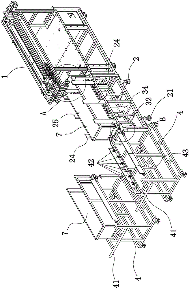
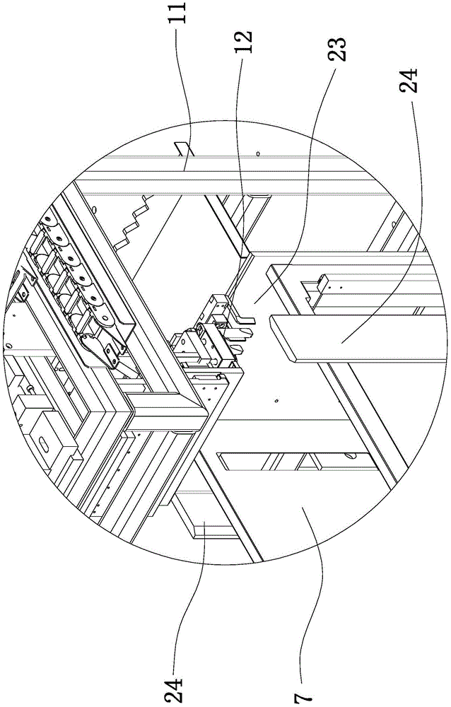
[0039] This example Figure 1 to Figure 6 As shown, the medical assembly machine includes a catheter feeding device 1 capable of picking up catheters. The catheter feeding device 1 includes a frame 11 and a feeding claw 12 arranged at one end of the frame 11 . The feeding device includes a feeding frame 2 and a movable feeding cart 4 arranged on one side of the conduit feeding device 1 .
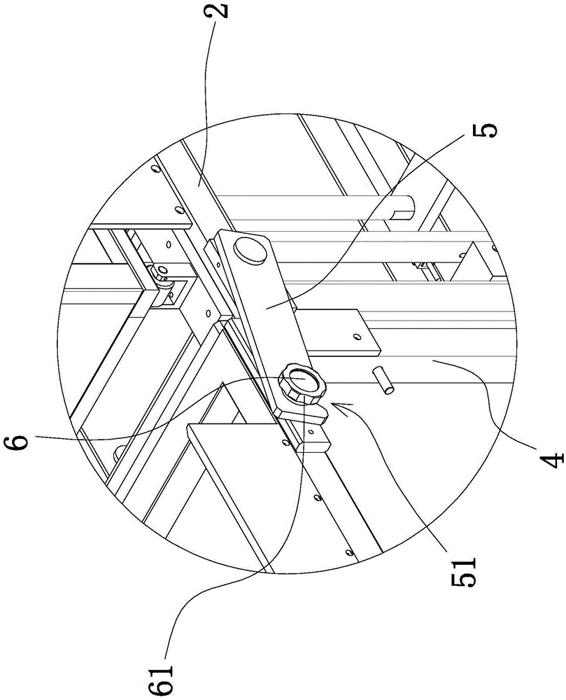
[0040] The feeding rack 2 is a frame structure, and the lower end of the feeding rack 2 is supported and fixed by four fixing seats 21; Below, a baffle plate 23 is fixed at one end of the conveying channel one 22 on the loading rack 2 . Conveying material channel one 22 is guide rail one or the roller group one that is made up of several rollers. When adopting guide rail one, the bottom of the case of material box 7 has a chute matched with guide rail one, and conveys material box 7 by guide rail one; The rollers are formed, and the case bottom surface of the material box 7 abuts against ...
Embodiment 2
[0052] The structure and principle of this embodiment are basically the same as that of Embodiment 1, the difference is that the positioning structure includes two guide plates and magnets, the two guide plates are respectively fixed on both sides of the loading rack, and the two guide plates protrude The two sides of the feeding rack form a guide channel, the magnet is fixed on the end face of the feeding rack between the two guide plates, and the end face where the feeding cart and the feeding rack abut is fixed with an adsorption device capable of magnetically interacting with the magnet. piece. The guide plate defines the position of the feeding trolley relative to the loading rack, and then the feeding trolley and the loading rack are positioned through the adsorption of the magnet and the adsorption block. When separating the feeding trolley and the loading rack, only a certain force is required, which is easy to operate.
Embodiment 3
[0054] The structure and principle of this embodiment are basically the same as that of Embodiment 1, the difference is that the positioning structure includes a bump fixed on the feeding cart and a groove set on the feeding rack, and the bump is fixed on the feeding cart and the upper On the end face of the opposite end of the material rack, the groove is located on the end face of the opposite end of the feeding rack and the feeding cart, and the projection can be inserted into the groove to fix the feeding cart and the feeding rack.
PUM
 Abstract
Description
Claims
Application Information
 - R&D
- Intellectual Property
- Life Sciences
- Materials
- Tech Scout
- Unparalleled Data Quality
- Higher Quality Content
- 60% Fewer Hallucinations
Browse by: Latest US Patents, China's latest patents, Technical Efficacy Thesaurus, Application Domain, Technology Topic, Popular Technical Reports.
© 2025 PatSnap. All rights reserved.Legal|Privacy policy|Modern Slavery Act Transparency Statement|Sitemap|About US| Contact US: help@patsnap.com


