
Front end support adjustable variable pitch device based on inclined hinge blade

A technology of hinged brackets and blades, which is applied in the control of wind turbines, engine functions, engines, etc., can solve the problems of complex force state and pitch change of the folding pitch drive device, and achieve simple structure, balanced force, and pitch change. way simple effect

Inactive Publication Date: 2016-04-20
TSINGHUA UNIV
View PDF6 Cites 19 Cited by
  • Summary
  • Abstract
  • Description
  • Claims
  • Application Information

AI Technical Summary

Problems solved by technology

There are two characteristics of this technology: one is the use of oblique folding blades, so its pitching method is the hinged rotation of the blades, because the hinged rotation axis of the blades forms an included angle with the reference axis of the main blade, that is, oblique folding When rotating, the blade will change the angle of attack relative to the incoming flow when it is tilted, folded and pitched, thus producing the effect of pitching; the second is to adopt a segmented blade structure, the main blade is a fixed blade, and the front blade is folded and pitched Blades, the driving device for folding and pitching will be placed on the segmented blades. If it is a three-bladed fan, three sets of driving devices are required. After the front blades are folded, due to the large rotational inertia force, the folding and pitching drive The stress state of the device becomes very complicated
Therefore, there needs to be enough space in the middle of the blade to properly place the device for tilting and folding the blade to provide the driving power for the folding of the blade, and it must also have sufficient strength to ensure safety under stress, which gives the device Applications present greater challenges

Method used


Image

  • Front end support adjustable variable pitch device based on inclined hinge blade
  • Front end support adjustable variable pitch device based on inclined hinge blade
  • Front end support adjustable variable pitch device based on inclined hinge blade

Examples


Embodiment Construction

[0020] Below in conjunction with accompanying drawing, structure of the present invention and specific embodiment are described further:

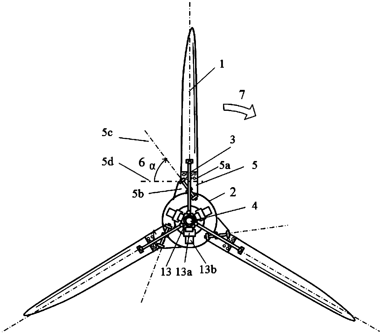
[0021] figure 1 Front view of a front-end support adjustable pitch device based on inclined hinged blades provided by the present invention, the device includes blade 1, hub 2, fan main shaft 8, inclined hinge assembly 5, front-end support connection assembly 3 and front-end pitch Adjustment assembly 4, the blade of the wind power generator device is an inclined hinged blade 1, the root of the blade is connected to the hub 2 through an inclined hinged assembly 5, and the front end support connection assembly 3 is connected to the front end pitch adjustment assembly 4 in the blade root area; The hinge axis tilt angle 6 formed by the hinge axis 5c of the blade hinge bracket 5a in the tilt hinge assembly 5 and the blade chord line 5d is between 45° and 75°.

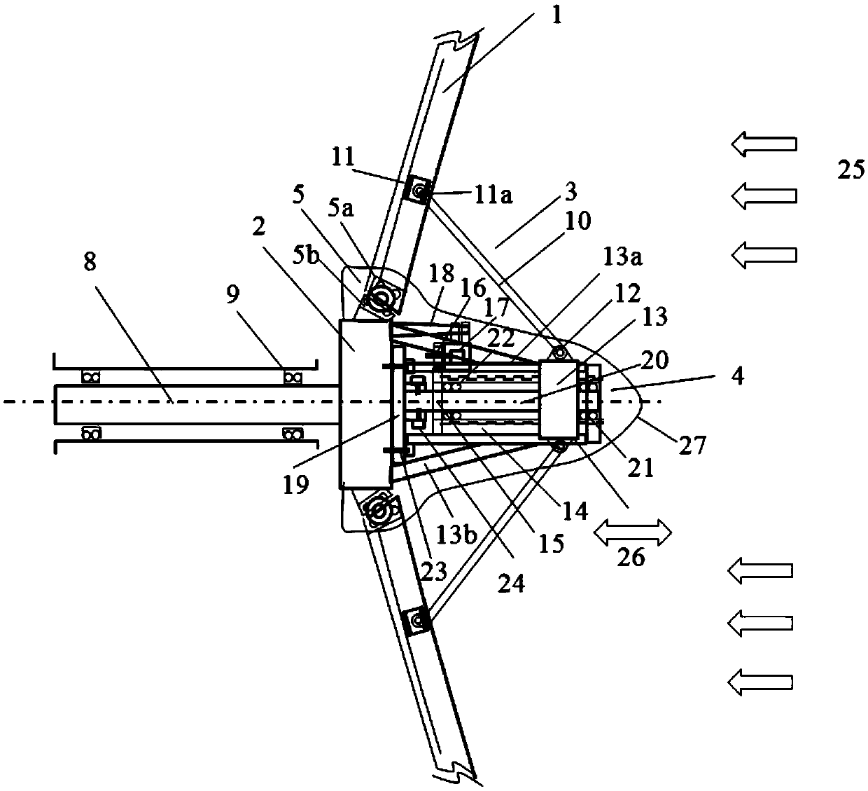
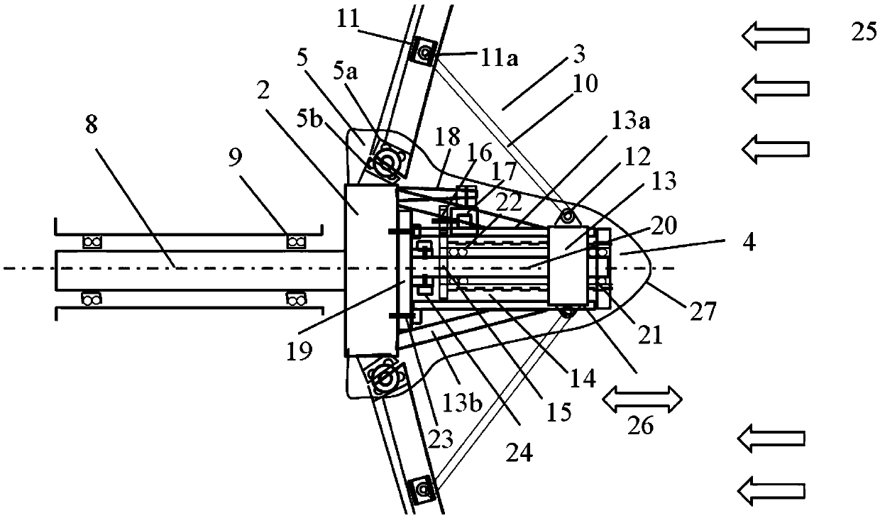
[0022] figure 2 Side view of a nose-supported adjustable pitch device based on til...


PUM


Abstract

The invention discloses a front end support adjustable variable pitch device based on an inclined hinge blade. The device comprises a blade, a hub, a fan main shaft, a front end support connecting assembly and a front end variable pitchadjusting assembly; the blade of a wind power generator device is the inclined hinge blade; the root part of the blade is connected with the hub through an inclined hinge assembly; the middle front part near the root part of the blade is connected with the front end variable pitchadjusting assembly through the front end support connecting assembly; the front end variable pitch adjusting assembly mainly consists of a base flange, a main support shaft, a lead screw and a variable pitchmotor; the variable pitch motor drives the lead screw, and the front end support connecting assembly enables the inclined hinge blade to generate out-plane tilting, so that a corresponding windward attach angle of the blade can be obviously changedto achieve a variable pitcheffect; as the blade adopts hinge support, and the root part connection bears no bending moment, the stress state of the fan device is greatly improved; and the device, provided by the invention, has such characteristics of simple structure, balanced stress and convenience for control, and is suitable for variable pitch adjustment of large / medium fans.

Description

technical field [0001] The invention relates to a blade structure of a large and medium-sized wind power generator, and belongs to the field of wind power generation equipment. Background technique [0002] Wind energy resources are very rich in the world, and almost all regions and countries have considerable wind energy reserves. Oil crises have occurred frequently in recent years, and the oil reserves and coal reserves of countries around the world will be exhausted within hundreds of years. Therefore, China, the United States, the United Kingdom, Spain and other countries have gradually shifted their attention to the development and utilization of new energy. As one of the important components of renewable energy, wind energy has attracted widespread attention from researchers and has also received strong support from governments of various countries. [0003] From the 1970s to modern times, the world's wind power has achieved amazing development. In 1996, the world's ...

Claims


Application Information

Patent Timeline
Patent Type & Authority Applications(China)
IPC IPC(8): F03D7/04
CPCF03D7/0224F03D7/0256F03D7/028F05B2260/76F05B2270/1033F05B2270/602F03D7/04Y02E10/72
Inventor 曾攀谢炜雷丽萍陆红亚
Owner TSINGHUA UNIV
Learn More