System and process for denitration by spraying ammonia gas in large-sized boiler high-temperature flue gas area

A technology of high-temperature flue gas and regional ammonia injection, applied in gas treatment, combustion product treatment, combustion methods, etc., can solve the problems of poor flue gas purification effect, increased ammonia escape, low denitrification rate, etc., and achieve temperature field control Accurate, high denitrification efficiency, maintain the effect of reaction time

Active Publication Date: 2016-04-20
杜梦凡
View PDF6 Cites 10 Cited by
  • Summary
  • Abstract
  • Description
  • Claims
  • Application Information

AI Technical Summary

Problems solved by technology

[0022] In order to solve the problems in the prior art of low denitrification rate, increased ammonia escape, secondary pollution, and poor flue gas purification effect, the present invention provides a large-scale boiler high-temperature flue gas area spraying ammonia gas denitrification system and process

Method used


Image

  • System and process for denitration by spraying ammonia gas in large-sized boiler high-temperature flue gas area
  • System and process for denitration by spraying ammonia gas in large-sized boiler high-temperature flue gas area
  • System and process for denitration by spraying ammonia gas in large-sized boiler high-temperature flue gas area

Examples


Embodiment 1

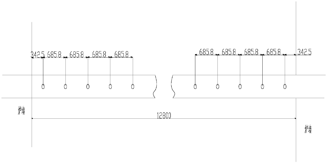
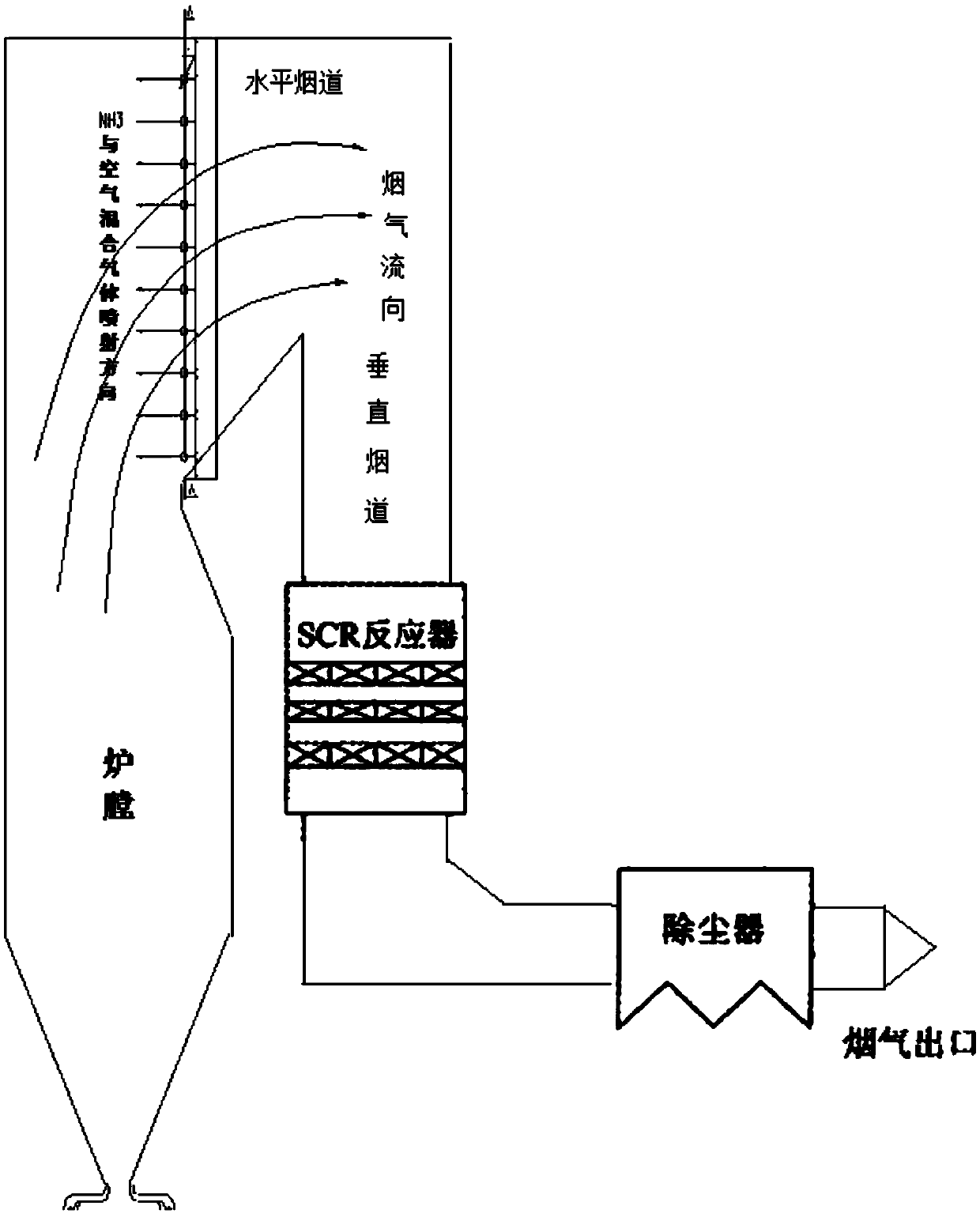
[0054] Embodiment 1: nozzle pipe longitudinal arrangement, the total length of nozzle pipe is 12800mm, offers 19 nozzle holes on this nozzle pipe, and the aperture of nozzle hole is 6-10mm, counts from the nozzle hole of nozzle input end, and aperture changes successively Larger, the pore diameter becomes larger in turn, so that the reducing agent is sprayed more uniformly, and the contact with the flue gas is more uniform, without bias, the purification of the flue gas is more thorough, and at the same time, it can further prevent ammonia from escaping.

[0055] A. Preparation of ammonia gas: ammonia gas is obtained by evaporating liquid ammonia, which is temporarily stored in the reducing agent storage tank;

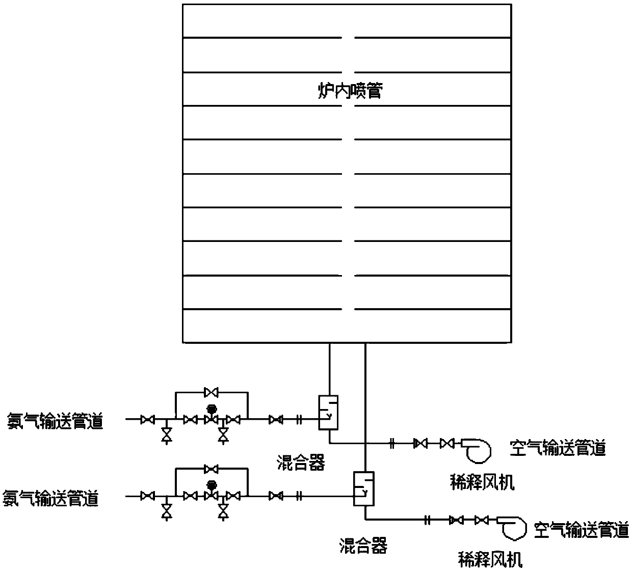
[0056] B. Primary denitrification: the ammonia gas output from the reducing agent storage tank is transported to the mixer through the ammonia gas delivery pipeline, and at the same time, the dilution fan is used to transport the air to the mixer through the air deliver...

Embodiment 2

[0059] Embodiment 2: nozzle pipe is horizontally arranged, and the total length of every nozzle pipe is 6300mm, offers 10 nozzle holes on this nozzle pipe, and the aperture of nozzle hole is 20-30mm, counts from the nozzle hole of nozzle input end, aperture become larger in turn.

[0060] A. Preparation of ammonia gas: ammonia gas is obtained by evaporating liquid ammonia, which is temporarily stored in the reducing agent storage tank;

[0061] B. Primary denitrification: the ammonia gas output from the reducing agent storage tank is transported to the mixer through the ammonia gas delivery pipeline, and at the same time, the dilution fan is used to transport the air to the mixer through the air delivery pipeline, and the ammonia and air are in the mixer After mixing, control the flow of ammonia and air by controlling the valves and flowmeters on the ammonia delivery pipeline and air delivery pipeline, so that the volume ratio of ammonia to air in the mixture is 4%-10%, and th...

Embodiment 3

[0064] Embodiment 3: nozzle pipe longitudinal arrangement, the total length of every nozzle pipe is 13000mm, offers 21 nozzle holes on this nozzle pipe, and the aperture of nozzle hole is 10-15mm, counts from the nozzle hole of nozzle input end, aperture become larger in turn.

[0065] A. Preparation of ammonia gas: ammonia gas is obtained by evaporating liquid ammonia, which is temporarily stored in the reducing agent storage tank;

[0066] B. Primary denitrification: the ammonia gas output from the reducing agent storage tank is transported to the mixer through the ammonia gas delivery pipeline, and at the same time, the dilution fan is used to transport the air to the mixer through the air delivery pipeline, and the ammonia and air are in the mixer After mixing, control the flow of ammonia and air by controlling the valves and flowmeters on the ammonia delivery pipeline and air delivery pipeline, so that the volume ratio of ammonia to air in the mixture is 5%-8%, and then u...


PUM

PropertyMeasurementUnit
lengthaaaaaaaaaa

Abstract

The invention belongs to the technical field of flue gas denitration and relates to a system for denitration by spraying ammonia gas in a large-sized boiler high-temperature flue gas area. A boiler comprises a horizontal flue and a vertical flue. The system comprises an SNCR (selective non-catalytic reduction) system provided with a reducing agent injector, the reducing agent injector is a spray pipe disposed on the transverse section of the horizontal flue, an input end of the spray pipe is connected with a reducing agent conveyer, the other end of the spray pipe is closed, and the wall of the spray pipe opposite to flue gas is provided with a spray hole. The invention also discloses a denitration process for denitration treatment using the system, the denitration treatment with the system gives high denitration rate and low ammonia escape quantity as well as full flue gas purification, this product is applicable to present coal-consuming boilers for thermal power generation, iron and steel, chemicals, cements and the like, and satisfactory NOx emission index of these boilers can be ensured.

Description

technical field [0001] The invention belongs to the technical field of flue gas denitrification, and relates to the technology of using ammonia gas for denitrification, and specifically relates to the ammonia gas denitrification system and denitrification process in the high temperature flue gas area of ​​large boilers. Through the denitrification treatment of this system and this process, the denitrification rate High, less ammonia escape, fully achieve the effect of purifying flue gas, this product can be applied to coal-consuming boilers such as thermal power generation, steel, chemical industry, cement, etc., can ensure that its NOx emission indicators meet the requirements of environmental protection. Background technique [0002] The current denitrification process using ammonia as a reducing agent is mainly divided into selective catalytic reduction (SCR) and selective non-catalytic reduction (SNCR). Selectivity means that the flue gas denitrification catalyst selecti...

Claims


Application Information

Patent Timeline
Patent Type & Authority Applications(China)
IPC IPC(8): F23J15/02B01D53/86B01D53/76B01D53/56
CPCB01D53/56B01D53/76B01D53/8631B01D2251/2062B01D2257/404B01D2258/0283F23J15/02F23J2215/10F23J2219/10
Inventor 杜梦凡程子衿
Owner 杜梦凡
Why Eureka
Try Eureka