
Control method of combined heat recovery system of water source heat pump and plate heat exchanger

A technology of plate heat exchangers and water source heat pumps, applied in heat recovery systems, fluid heaters, cleaning heat transfer devices, etc., can solve problems such as large temperature difference changes, large temperature difference water discharge, etc., to prolong service life and solve seasonal problems The effect of temperature difference change and stable working conditions

Active Publication Date: 2019-01-04
中盈绿能机电股份有限公司
View PDF6 Cites 0 Cited by
  • Summary
  • Abstract
  • Description
  • Claims
  • Application Information

AI Technical Summary

Problems solved by technology

[0005] In order to overcome the deficiencies in the above-mentioned prior art, the present invention provides a control method for a combined heat recovery system of a water source heat pump and a plate heat exchanger, which effectively solves the problem of large temperature difference at the heat source side and seasonal large temperature difference at the use side. And achieve the purpose of stable operating flow, stable heating conditions, water saving and electricity cost reduction

Method used


Image

  • Control method of combined heat recovery system of water source heat pump and plate heat exchanger
  • Control method of combined heat recovery system of water source heat pump and plate heat exchanger
  • Control method of combined heat recovery system of water source heat pump and plate heat exchanger

Examples


Embodiment 1

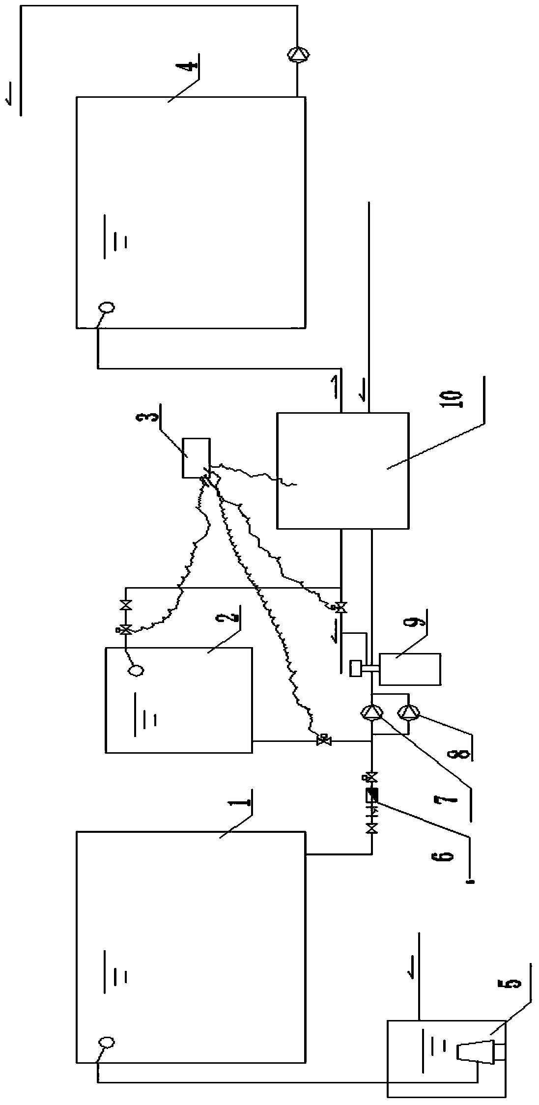
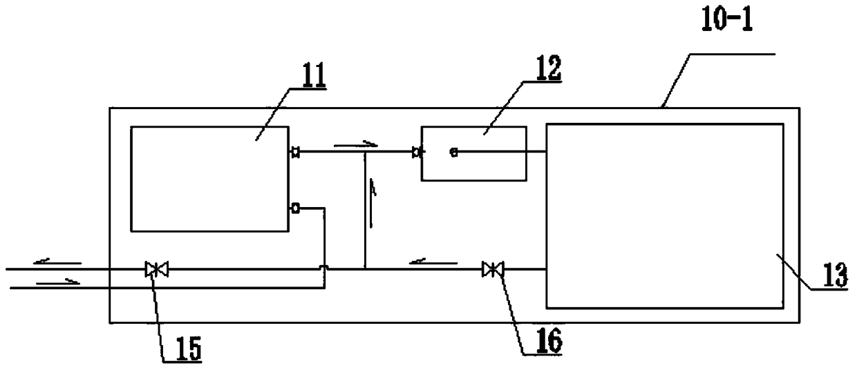
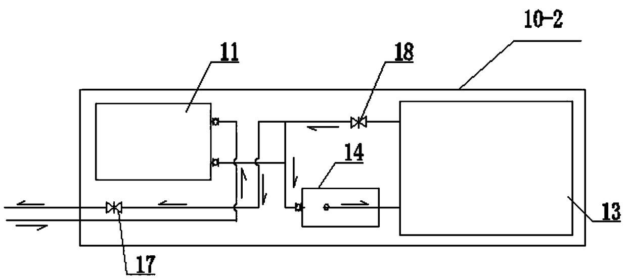
[0035] Such as Figure 1-3 As shown, a combined heat recovery system of a water source heat pump and a plate heat exchanger, the whole system includes a waste water collection tank 1, a sand tank filter 9, a heat exchange unit unit 10, a hot water tank 4, an electric control system 3 and a backwash water tank 2. The sand tank filter 9 is respectively connected to the waste water collection tank 1 and the backwash water tank 2 through pipelines, and the heat source side of the heat exchange unit 10 is respectively connected to the drain pipe and the sand tank filter 9, and the use side is respectively Connect running water pipe and hot water tank 4, on the pipeline between described waste water collecting tank 1 and sand tank filter 9, flow meter 6 and pressurized water pump group are also installed, and described pressurized water pump group is composed of pressurized water pump A7 and pressurized water pump B8 are connected in parallel;

[0036] The heat exchange unit 10 inc...

Embodiment 2

[0040] Such as Figure 1-3 As shown, a control method for a combined heat recovery system of a water source heat pump and a plate heat exchanger includes the following steps:

[0041] A. Start the control process

[0042] A1, the submersible pump in the sump 5 is controlled by the liquid level of the sump 5 to start, and the waste water is transported to the waste water collection tank 1, and the electric control system 3 collects the water level and temperature signal of the waste water collection tank 1 in real time;

[0043] A2. All solenoid valves are closed when they are not working;

[0044]A3. Detect the water level of the waste water collection tank 1. When the water level is within the control value range, open the solenoid valve on the outlet pipe of the waste water collection tank 1, start the pressurized water pump A7 or pressurized water pump B8 in turn, and open the tap water inlet pipe at the same time. solenoid valve;

[0045] A4. Turn on the circulating wat...

Embodiment 3

[0056] Such as Figure 1-3 As shown, a combined heat recovery system of a water source heat pump and a plate heat exchanger, the whole system includes a waste water collection tank 1, a sand tank filter 9, a heat exchange unit unit 10, a hot water tank 4, an electric control system 3 and a backwash water tank 2. The sand tank filter 9 is respectively connected to the waste water collection tank 1 and the backwash water tank 2 through pipelines, and the heat source side of the heat exchange unit 10 is respectively connected to the drain pipe and the sand tank filter 9, and the use side is respectively Connect running water pipe and hot water tank 4, on the pipeline between described waste water collecting tank 1 and sand tank filter 9, flow meter 6 and pressurized water pump group are also installed, and described pressurized water pump group is composed of pressurized water pump A7 and pressurized water pump B8 are connected in parallel;

[0057] The heat exchange unit 10 inc...


PUM


Abstract

The invention discloses a water source heat pump and plate heat exchanger combined heat recovery system and a control method thereof. The system comprises a wastewater collecting tank, a sand filter, a heat exchange unit, a hot water tank, an electronic control system and a back flush water tank; the sand filter is connected with the wastewater collecting tank and the back flush water tank through pipelines, the heat source side of the heat exchange unit is connected with a drain pipe and the sand filter, the usage side of the heat exchange unit is connected with a tap water pipe and the hot water tank, and the heat exchange unit comprises a plate heat exchanger, a water source heat pump, a circulating water pump and a flow controller. According to the system, the heat source side and the heating side achieve full heat exchange at the plate heat exchanger and then achieve heat energy transfer in the water source heat pump unit, the heat exchanger effect is significantly improved, working power is saved by 25%-50% compared with a single heat pump unit, the comprehensive energy efficiency ratio is 6-7, and the efficiency cannot be achieved by a small heat pump unit. According to the system, the problem that yielding water in the heat source side is large in temperature difference is solved, and the service life is prolonged.

Description

technical field [0001] The invention belongs to a water source heat pump system, in particular to a water source heat pump system which improves heat recovery efficiency and reduces power consumption. Background technique [0002] Usually, the waste water source heat pump directly connects the heat source side to the evaporation side of the heat pump when the waste water heat energy is recovered, that is, the inlet water temperature of the evaporator side of the water source heat pump is the initial temperature of the heat source. The temperature on the heat source side of the waste water is generally 30°C or higher. In order to better recover the energy on the heat source side, the outlet water temperature on the heat source side needs to be lowered. However, the large temperature difference on the heat source side will affect the structural form of the water source heat pump unit. Usually, the standard model water source The temperature difference between the inlet and out...

Claims


Application Information

Patent Timeline
Patent Type & Authority Patents(China)
IPC IPC(8): F24H4/04F24H9/00F24H9/20F28G9/00
CPCY02B30/52
Inventor 马志勇谢飞
Owner 中盈绿能机电股份有限公司
Learn More