A solar heat collection system using light guide cables to transmit concentrated light beams

A solar heat collection and optical cable technology, which is applied in the field of solar heat collection systems, can solve the problems that tower heat collection cannot fully and effectively utilize solar energy and unfavorable engineering construction, so as to increase the utilization rate of sunlight, improve system stability, reduce The effect of engineering difficulty

Active Publication Date: 2017-12-08
HUANENG CLEAN ENERGY RES INST +1
View PDF9 Cites 0 Cited by
  • Summary
  • Abstract
  • Description
  • Claims
  • Application Information

AI Technical Summary

Problems solved by technology

At present, an important factor that limits the improvement of the efficiency of thermal power generation is the efficiency of the thermal tower.
In order to obtain greater power and a higher temperature field, it is necessary to use more condensers to concentrate more sunlight on the heat absorber on the top of the heat collection tower. At the same time, in order to receive reflections from more reflectors If there is no light, it is necessary to build the heat collector tower very high, which is extremely unfavorable for engineering construction and equipment operation.
Moreover, due to the influence of the cosine effect, the tower collector cannot fully and effectively utilize the solar energy in the collector field

Method used


Image

  • A solar heat collection system using light guide cables to transmit concentrated light beams
  • A solar heat collection system using light guide cables to transmit concentrated light beams

Examples


Embodiment Construction

[0029] The implementation of the present invention will be described in detail below in conjunction with the drawings and examples.

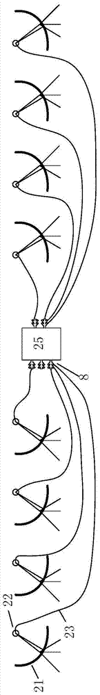
[0030] like figure 1 As shown, the heat collection system of the present invention is composed of a curved condenser lens 21, a light guide head 22, a light guide cable 23, a light receiving head 8, and a heat absorber 25. The system adopts a large number of curved condenser mirrors 21 arranged to form a curved condenser mirror array. Each curved condenser mirror 21 has the same specification and is arranged around the heat absorber 25 according to a certain rule.

[0031] Each curved concentrator 21 can gather the parallel sun rays on its own focal point. The light guide head 22 is positioned at the focal point of the curved concentrator 21. The light guide head 22 is connected to one end of the light guide cable 23, and the other end of the light guide cable 23 is the end. The light receiving head 8 is connected, and the light receiving head ...


PUM


Abstract

The invention provides a solar heat collection system capable of transmitting and focusing light beams by using a light guide cable, which can perform large-scale sunlight focusing and form a high-temperature temperature field inside a heat absorber to heat a working medium. The solar heat collection system is mainly composed of cambered surface condensing lenses, light guide heads, light guide cables, light receiving heads and a heat absorber. The cambered surface condensing lenses focus parallel sunlight to the focal point, the focused light rays are guided by the light guide head into the light guide cable, and the light rays are transmitted to the light receiving head installed on the heat absorber via the light guide cable by utilizing the total reflection principle and guided by the light receiving head to the inner cavity of the heat absorber. The plurality of cambered surface condensing lenses constitute an array; the sunlight focused by each cambered surface condensing lens is transmitted to the inner cavity of the heat absorber via one light guide cable, the light rays output by the tail ends of all the light guide cables are superposed inside the heat absorber and irradiate the working medium and inner wall surface to form high temperature; and the flowing working medium is heated so as to take the heat out, thereby implementing solar heat collection utilization. The solar heat collection system is especially suitable for solar heat collection power plants.

Description

technical field [0001] The invention belongs to the technical field of solar heat collection and power generation, and in particular relates to a solar heat collection system which adopts an optical cable to transmit concentrated light beams. Background technique [0002] On the one hand, the level of human energy consumption continues to increase, on the other hand, conventional fossil energy is increasingly exhausted, and the pollutant emissions associated with conventional fossil energy are increasingly unable to meet people's demand for future energy. Solar energy, as an inexhaustible new clean energy, is getting more and more attention, and the development of solar energy is making progress day by day. Among them, solar power generation is an advanced development and application of solar energy. It converts solar energy into electrical energy through certain means to meet the electricity demand of modern society. Currently popular solar power generation is mainly divid...

Claims


Application Information

Patent Timeline
Patent Type & Authority Patents(China)
IPC IPC(8): F24J2/10F24J2/06F24J2/38F24J2/46F24S23/00F24S23/70F24S50/20
CPCF24S23/12F24S23/70F24S50/20F24S70/30F24S2023/87Y02E10/47
Inventor 陈新明闫姝史绍平王保民许世森
Owner HUANENG CLEAN ENERGY RES INST
Why Eureka
Try Eureka