
Satellite-borne interference imaging altimeter antenna

An interferometric imaging and altimeter technology, applied in radio wave measurement systems, radio wave reflection/re-radiation, utilization of re-radiation, etc. problem, to achieve the effect of reducing dimensionality, simplifying the structure of the antenna system, and reducing the complexity

Active Publication Date: 2021-07-16
NAT SPACE SCI CENT CAS
View PDF9 Cites 3 Cited by
  • Summary
  • Abstract
  • Description
  • Claims
  • Application Information

AI Technical Summary

Problems solved by technology

[0005] The current space-borne interferometric imaging altimeter antenna distance observation is inconsistent, the feed network is complicated, the processing is difficult, and the working bandwidth is narrow, which is not conducive to the high-precision observation of mesoscale ocean phenomena.

Method used


Image

  • Satellite-borne interference imaging altimeter antenna
  • Satellite-borne interference imaging altimeter antenna
  • Satellite-borne interference imaging altimeter antenna

Examples


example

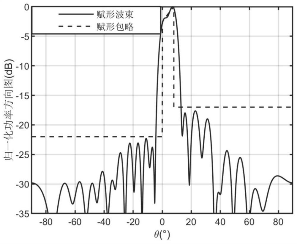
[0127] In this example, in the given array interface L x × L y = 10.5λ×109.5λ half-wavelength evenly arranged antenna elements, along the distance direction and azimuth direction respectively to achieve a desired shaped beam and pencil beam, where the incident angle area required in the distance direction is [0°, 7°], The index requirements of the shaped area can be deduced from the backscatter coefficient of the sea surface, that is, the maximum beam direction is 7°, and with the increase of the incident angle, the power pattern of the shaped beam increases by 7dB, and the ripple jitter in the shaped area does not change. More than 0.5dB, and require the sidelobe level SLL on the left and right sides of the shaped beam d They are -22dB and -18dB respectively, the phase difference of each array element does not exceed 300°, and the amplitude dynamic range is not less than 0.2; the azimuth is required to realize the Taylor weighted pattern characteristic of -25dB. Adopt a kin...


PUM


Abstract

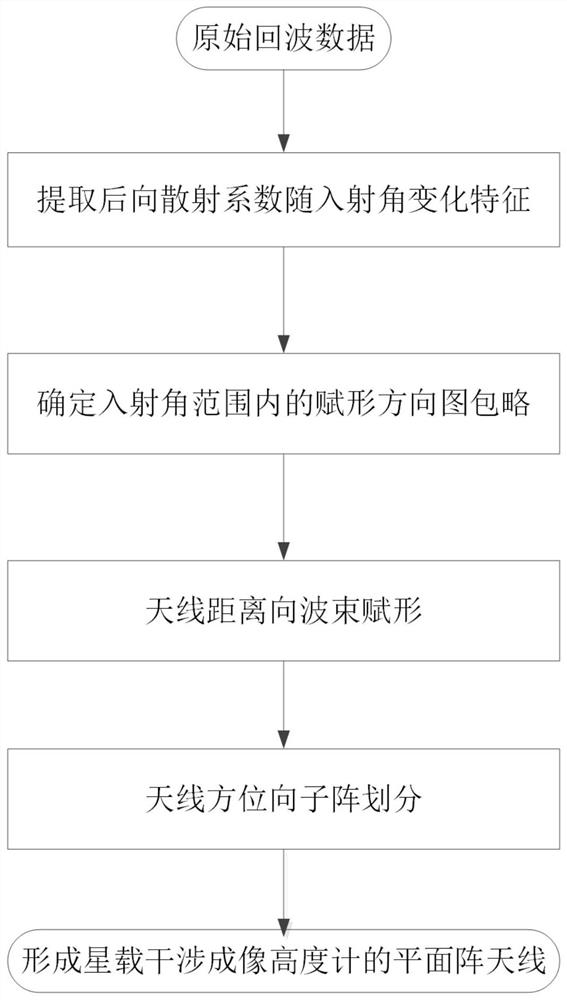
The invention discloses a spaceborne interference imaging altimeter antenna, which is a shaped beam planar array antenna given based on a physical size. The antenna comprises a plurality of sub-arrays, wherein each sub-array comprises a plurality of array elements, array element excitation in each sub-array is equal in amplitude and same in phase, the distance direction of the antenna adopts a shaped beam design, a shaped beam and excitation are determined according to a shaped curve, a sidelobe level, an antenna array element and an amplitude-phase constraint index within an incident angle range; the sub-array division technology is adopted in azimuth design of the antenna, a pen-shaped beam with expected Taylor weighted directional diagram characteristics is achieved through sub-array level amplitude weighting, and excitation parameters of the antenna are determined according to design results of the distance direction and the azimuth direction according to the separable planar array forming principle. According to the antenna, the antenna distance direction is subjected to shaped beam synthesis, interference height measurement precision can be improved, the azimuth direction is subjected to subarray division, the antenna bandwidth can be improved, the whole antenna system structure is simplified, and the hardware implementation cost and engineering difficulty are reduced.

Description

technical field [0001] The invention relates to the field of wireless communication, in particular to a satellite-borne interference imaging altimeter antenna. Background technique [0002] The spaceborne interferometric imaging altimeter is a microwave remote sensor that uses small-angle incidence and short-baseline interference to achieve high-precision observations of land and sea surfaces. It is one of the main remote sensors for marine dynamic environment observations (literature [1]: Y. J. Jiang, X. Zhang, K. Xu, J. Yan, C. Jiang, et al, "Design and preliminary experiment of china imaging altimeter," Microwave Remote Sensing of the Atmosphere and Environment III, pp.190-199, 2003) . In 2016, the world's first space-borne interferometric imaging altimeter was launched with the Tiangong-2 space laboratory, breaking through the limitations of traditional altimeters that can only perform one-dimensional line observation of sub-satellite points along the flight direction, ...

Claims


Application Information

Patent Timeline
Patent Type & Authority Applications(China)
IPC IPC(8): G01S13/88G01S13/90G01S7/02
CPCG01S7/02G01S13/882G01S13/9023
Inventor 赵晓雯张云华董晓
Owner NAT SPACE SCI CENT CAS
Learn More