A spectrophotometer

A technology of spectrophotometer and colorimeter, which is applied in the field of spectrophotometer, can solve problems such as unevenness, diffuse reflection of integrating sphere, insufficient illumination of the sample surface, etc., and achieve the effect of improving accuracy

Active Publication Date: 2017-09-15
HANGZHOU EVERFINE PHOTO E INFO
View PDF2 Cites 1 Cited by
  • Summary
  • Abstract
  • Description
  • Claims
  • Application Information

AI Technical Summary

Problems solved by technology

But the technical scheme of US005859709A ( figure 2 The light utilization rate of the second light source in ) is low, the illumination on the sample surface is insufficient and there is secondary diffuse reflection on the inner wall of the integrating sphere, and the repeatability is poor
JP4400538B2( image 3 ) has improved the second illumination system, but the second illumination light source illuminates the sample surface through a diffuser and a focusing device. Although this structure improves the light source utilization rate and signal-to-noise ratio, it has several significant disadvantages: first It is to directly image the light source at the sampling window at one time, but because the light shape of the light source is usually uneven, the light shape of the light source projected on the sample to be tested is also uneven, which will directly affect the SCE measurement results Although the size of the spot can be adjusted with an aperture, the defects caused by the unevenness of the light source will be more prominent when the spot is small; secondly, since there is only one aperture for adjusting the size of the spot in this structure, it is impossible to realize the adjustment of the spot The adjustment of the strength leads to obvious differences in the strength of the signal received by the detector when measuring samples with a large difference in reflectivity, the dynamic range is small, and the test accuracy is not high

Method used


Image

  • A spectrophotometer
  • A spectrophotometer
  • A spectrophotometer

Examples


Embodiment 1

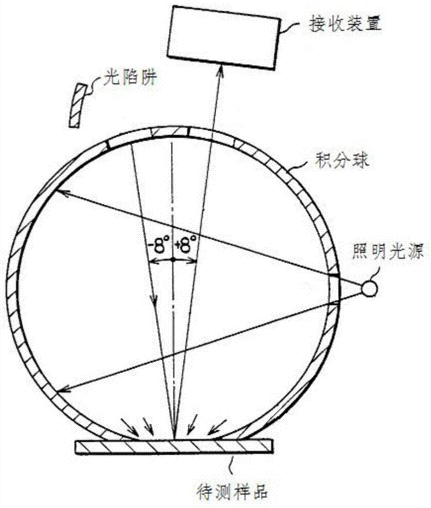
[0038] Such as Figure 4 As shown, this embodiment discloses a spectrophotometer, which is composed of an integrating sphere 1, an optical receiving device 3, a first illumination system 4, and a second illumination system 5. A sampling window 13 is opened at the bottom of the integrating sphere 1, and an extinction part 7 is provided on the inner wall of the integrating sphere 1 near the edge of the sampling window 13, where the extinction part 7 is a black coating with a reflectivity lower than 8% (such as Figure 8 As shown), the remaining part of the inner wall of the integrating sphere 1 is coated with a white coating with high reflectivity. A light source entrance 11 is opened on the integrating sphere 1 which is offset by -8° from the center normal of the sampling window 13, and the light emitted by the second illumination system 5 illuminates the sampling window 13 through the light source entrance 11; A measuring window 12 is opened at the integrating sphere 1 with a li...

Embodiment 2

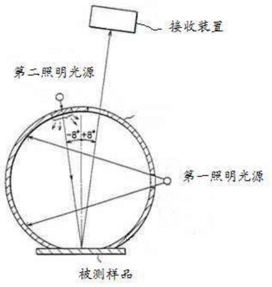
[0042] Such as Figure 5 As shown, the difference from Embodiment 1 is that the first illumination system 4 in this embodiment is placed in the integrating sphere, and there is no need to open a corresponding incident slit on the side wall of the integrating sphere 1 at this time. The light emitted by the first illumination system 4 is directly reflected by the integrating sphere 1 for multiple times, and then illuminates the surface of the sample to be measured in a diffuse incident manner. Compared with the solution in embodiment 1 where the first lighting system 4 is placed outside the integrating sphere, this embodiment is suitable for the first lighting system 4 with a small volume. What is more important is that the number of openings is less than that in the first embodiment. Achieve better mixing effect.

Embodiment 3

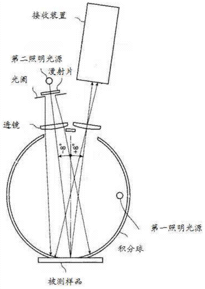
[0044] Such as Image 6 As shown, the difference from Embodiments 1 and 2 is that this embodiment also includes a reflector device. The reflector device is located outside the light entrance 11 of the integrating sphere 1 and is arranged along the optical path behind the second illumination system 5. The light emitted by the condenser 53 of the second illumination system 5 is first reflected by the reflecting device and then projected through the light entrance 11 to the first reflecting area 6 of the inner wall of the integrating sphere 1. The optical axis and optics of the light reflected by the first reflecting area 6 The optical axis of the receiving device 3 is in a mirror symmetry relationship along the center normal of the sampling window 13. The light reflected by the first reflection area 6 is projected to the surface of the sample 2 to be tested and is received by the optical receiving device 3 after being affected.


PUM


Abstract

The invention discloses a light-splitting color photometer. Test conditions compatible for SCI and SCE are achieved by combination of a dual-light-source system consisting of a first illuminating system and a second illuminating system. The second illuminating system in the dual-light-source system comprises a second illuminating light source, a front lens, a light collecting lens and two adjustable light diaphragms; light emitted by the second illuminating light source is imaged near the light collecting lens by the front lens; the light collecting lens is used for imaging the front lens near a target area; the light emitted by the second illuminating light source is imaged, then the light shape of the light source is more uniform, namely the light source irradiated on a tested sample is more uniform; test data obtained on the basis of the light source is more accurate; the measurement reproducibility is better; the size and the intensity of light spots projected to the tested area can also be adjusted by adjusting the two light diaphragms; the colors of various objects are effectively and accurately measured; in addition, a light eliminating part is also arranged at the periphery of a tested sample taking area; the level of stray light is further reduced; the test accuracy is improved.

Description

【Technical Field】 [0001] The invention relates to the technical field of color measurement, in particular to a spectrophotometer. 【Background technique】 [0002] The d / 8 measurement geometry recommended by CIE includes two structures: SCI (contains the specular reflection of the surface of the tested sample) and SCE (eliminates the specular reflection of the surface of the tested sample). The SCI measurement result has nothing to do with the surface gloss of the material, and the data is generally used for color matching; SCE excludes specular reflection light, which is close to the result of eye observation of color, and is generally used for color acceptance and quality control. In the existing d8 spectrophotometer, the light emitted by the light source is mixed in the integrating sphere to diffusely illuminate the sample, and a receiving device is set at a position offset by 8° from the normal of the sample, and is connected to the wall of the integrating sphere. There is a l...

Claims


Application Information

Patent Timeline
Patent Type & Authority Patents(China)
IPC IPC(8): G01J3/46
CPCG01J3/46
Inventor 潘建根黄艳黄英
Owner HANGZHOU EVERFINE PHOTO E INFO
Why Eureka
Try Eureka