Method for monitoring using state of large medical equipment based on hall current and image changing

A technology of medical equipment and Hall current, which is applied in the direction of measuring electrical variables, voltage/current isolation, and measurement using digital measurement technology. It can solve problems such as poor accuracy, electric shock threats to staff safety, and breakdown of line insulation. Achieve the effects of getting rid of manual intervention, facilitating real-time monitoring, and good linearity

Active Publication Date: 2016-04-20
HANGZHOU FIRST PEOPLES HOSPITAL
View PDF5 Cites 8 Cited by
  • Summary
  • Abstract
  • Description
  • Claims
  • Application Information

AI Technical Summary

Problems solved by technology

[0010] (1) The feedthrough transformer is used as the circuit component for current measurement. If the AC current transformer is open circuited, high voltage will be generated. The influence of distortion, multiple harmonics, non-sine waves, etc., makes the accuracy of current transformer measurement results poor
[0011] (2) The establishment of the classification model requires an independent test mode. This test mode requires the manual intervention of the staff. If the number of equipment in the hospital is large, there will be a lot of duplication of labor, and it is difficult to popularize and apply
[0016] There is no significant difference in the current used by large-scale medical equipment in special states such as patient information operation and standby state. In the prior art, it is impossible to accurately distinguish between
Furthermore, in the prior art, if the use state of the large medical equipment is judged to be in standby mode, and it is in the standby state for a long time, it is still necessary to manually shut down the large medical equipment.

Method used


Image

  • Method for monitoring using state of large medical equipment based on hall current and image changing
  • Method for monitoring using state of large medical equipment based on hall current and image changing
  • Method for monitoring using state of large medical equipment based on hall current and image changing

Examples


Embodiment Construction

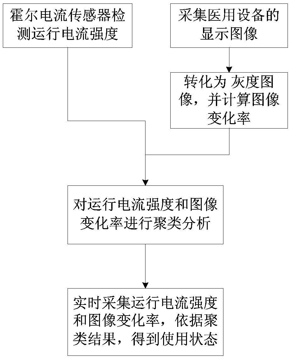
[0065] The method for monitoring the use status of large medical equipment based on Hall current and image changes of the present invention will be described in detail below in conjunction with the accompanying drawings.

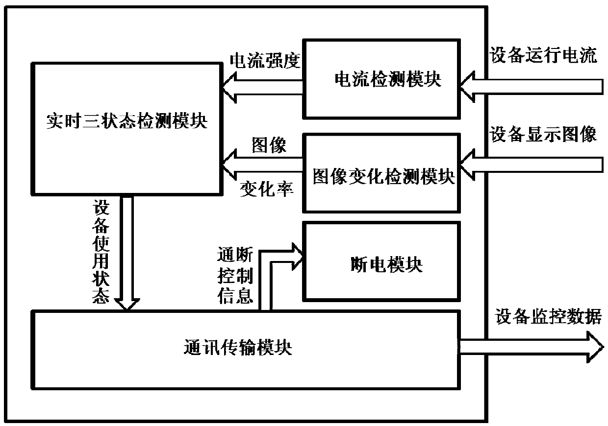
[0066] Such as image 3 As shown, the monitoring system structure for realizing the method provided by the present invention includes: a current detection module, an image change detection module, a real-time three-state detection module, a communication transmission module and a power-off control module; wherein the current detection module, the image change detection module and the real-time The three-state detection module is connected by communication, the real-time three-state detection module is connected with the communication transmission module, and the power-off control module is connected with the communication transmission module.

[0067] The current detection module converts the magnetic field generated by the alternating current into a linear ...


PUM


Abstract

The invention discloses a method for monitoring a using state of large medical equipment based on a hall current and image changing. The method comprises: step one, a hall current sensor detects the operating current intensity of large medical equipment and a display image of the large medical equipment is also collected, the display image is converted into a gray level image, and an image changing rate is calculated; step two, a cluster analysis is carried out on the operating current intensity and the image changing rate and thus the operating current intensity and the image changing rate correspond to different using states, wherein the using states at least include a shutdown state, a standby state, and an operating state; and step three, the operating current intensity and the image changing rate of the large medical equipment are collected in real time, and a corresponding using state is obtained based on a cluster result. Therefore, a non-linear state analysis can be carried out on the using state of the large medical equipment automatically without any manual intervention and accurate using state information also can be obtained.

Description

technical field [0001] The invention relates to the technical field of equipment monitoring, in particular to a method for monitoring the use status of large medical equipment based on Hall current and image changes. Background technique [0002] With the continuous improvement of my country's medical system structure, the number of large and expensive medical equipment and instruments in large and medium-sized hospitals is also increasing. Therefore, how to improve the use efficiency of large medical equipment and improve the comprehensive benefits of hospitals is a key issue in the management of medical equipment. topics that should be explored in depth. [0003] In the daily management of hospitals, equipment such as radiology and ultrasound are basically managed manually to make statistics on the daily start-up and stop of the equipment. Manual statistics are relatively subjective and cannot be monitored in real time. In this process, if the manual management is slightly...

Claims


Application Information

Patent Timeline
Patent Type & Authority Applications(China)
IPC IPC(8): G01R19/25G01R15/20
CPCG01R15/202G01R19/25
Inventor 王清波虞成
Owner HANGZHOU FIRST PEOPLES HOSPITAL
Why Eureka
Try Eureka