
Low-altitude unmanned aerial vehicle microwave damaging device

A UAV and microwave technology, which is applied to defensive devices, offensive equipment, etc., can solve the problems of poor timeliness, poor response timeliness, and UAV damage, and achieves simple structure, convenient use, and good damage effect.

Inactive Publication Date: 2017-07-07
曹亚强
View PDF7 Cites 3 Cited by
  • Summary
  • Abstract
  • Description
  • Claims
  • Application Information

AI Technical Summary

Problems solved by technology

Its mechanism of action is the same as that of electronic jamming, but considering the preparation of my drone and the timing of takeoff and landing, the timeliness of countermeasures is poor
[0006] Conventional kinetic energy weapons and "Skynet" capture use physical means to damage and capture UAVs. While the timeliness is poor, certain requirements are placed on material support such as ammunition and capture nets, and the site and operation convenience are poor.

Method used


Image

  • Low-altitude unmanned aerial vehicle microwave damaging device
  • Low-altitude unmanned aerial vehicle microwave damaging device
  • Low-altitude unmanned aerial vehicle microwave damaging device

Examples


Embodiment 1

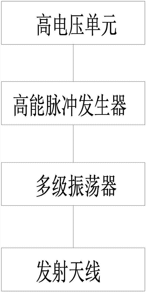
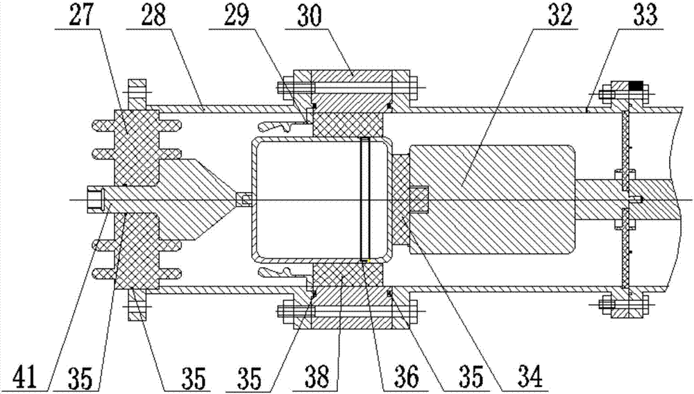
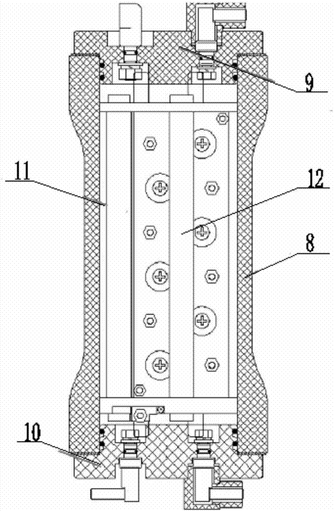
[0033] Such as Figures 1 to 6 As shown, the low-altitude UAV microwave damage device of the present invention includes a high-voltage unit, a high-energy pulse generator, a multistage oscillator and a transmitting antenna connected in sequence;

[0034] The high-voltage unit is used to positively and negatively charge the capacitor of the high-energy pulse generator, the high-voltage unit generates high-voltage pulses, and uses constant current charging to charge the large-capacity capacitor in the high-energy pulse generator;

[0035] The high-energy pulse generator outputs a high-voltage pulse to resonantly charge the multi-stage oscillator, and the amplitude and efficiency of the high-voltage pulse output by the high-energy pulse generator directly affect the amplitude and efficiency of the radio frequency signal generated by the multi-stage oscillator;

[0036] The multi-stage oscillator stores the energy of the high-voltage pulse output by the high-energy pulse generator...

Embodiment 2

[0040] As a preference, in order to better realize the present invention, further optimize on the basis of the above-mentioned embodiments, especially adopt the following arrangement structure: the high-voltage unit includes an IGBT inverter module and a transformer that cooperates with the IGBT inverter module. A voltage rectification module, the output end of the voltage transformation rectification module is connected with a high-energy pulse generator. It is worth noting that one end of the IGBT inverter module is connected to rectified DC power of about 300V, a stable AC power is obtained through the IGBT inverter module, and then a constant high-voltage DC power is output through transformation and rectification. The constant high-voltage DC power Provides electrical energy to the high energy pulse generator.

Embodiment 3

[0042] As a preference, in order to better realize the present invention, the above-mentioned embodiments are further optimized, and the following configuration structure is adopted in particular: the high-energy pulse generator adopts a Marx generator.


PUM


Abstract

The invention relates to the field of high-power microwaves, in particular to a low-altitude unmanned aerial vehicle microwave damaging device which is simple in structure, convenient to use and good in damaging effect. The low-altitude unmanned aerial vehicle microwave damaging device comprises a high-voltage unit, a high-energy pulser, a multi-stage oscillator and a transmitting antenna which are sequentially connected. According to the low-altitude unmanned aerial vehicle microwave damaging device, through cooperation of the high-voltage unit, the high-energy pulser, the multi-stage oscillator and the transmitting antenna, the transmitting antenna transmits high-energy microwaves, and the action mechanisms of an electronic system used for remotely attacking unmanned aerial vehicles in a noncontact mode and carried electronic devices for photographing, recording, videoing and the like are that through the radiation coupling effect of high-power microwave pulses, the pulse voltage greatly exceeding a rated operational voltage value on circuits and elements of a target electronic equipment are inducted, and a target is permanently damaged, so that the purpose of damaging the unmanned aerial vehicle is achieved, and the device has the characteristics of being simple in structure, convenient to use and good in damaging effect.

Description

technical field [0001] The invention relates to the field of high-power waves, in particular to a microwave damage device for low-altitude drones with simple structure, convenient use and good damage effect. Background technique [0002] While drones bring great convenience to human life, they also bring many safety problems. Especially with the improvement of technology and price reduction of domestic small UAVs such as DJI, the use of low-cost and low-altitude small UAVs for civilian use to reconnaissance and threat sensitive areas has gradually increased. In the military field, incidents of small UAVs arriving at low altitudes for reconnaissance are gradually increasing. In the civilian field, incidents of UAVs straying into airport take-off and landing routes are also emerging one after another, which greatly threatens military and public safety. In order to counter low-altitude drones, mainstream technologies at this stage include electronic jamming, laser weapons, "ki...

Claims


Application Information

Patent Timeline
Patent Type & Authority Applications(China)
IPC IPC(8): F41H11/02
CPCF41H11/02
Inventor 曹亚强曹建王磊王国卫梁捷高伟亮韩维侯学隆
Owner 曹亚强
Learn More