Connection test device, insulation test device and test system of universal test machine

A technology of conduction test and insulation test, which is applied in the direction of measuring device, electronic circuit test, and test of dielectric strength, etc. It can solve the problem that the measurement circuit cannot meet the test requirements, so as to improve the measurement accuracy, ensure stability, and achieve large-scale measurement. range effect

Active Publication Date: 2016-04-20
JOINT STARS TECH
View PDF5 Cites 13 Cited by
  • Summary
  • Abstract
  • Description
  • Claims
  • Application Information

AI Technical Summary

Problems solved by technology

[0004] However, in the test circuit of the existing universal testing machine, the measurement range of the continuity measurement circuit is about 10Ω~100Ω±10%, and the measurement range of the insulation test circuit is 1MΩ~50MΩ±10%. Higher and higher, the measurement circuit can no longer meet the test requirements during the carbon plate test

Method used


Image

  • Connection test device, insulation test device and test system of universal test machine
  • Connection test device, insulation test device and test system of universal test machine
  • Connection test device, insulation test device and test system of universal test machine

Examples


Embodiment 1

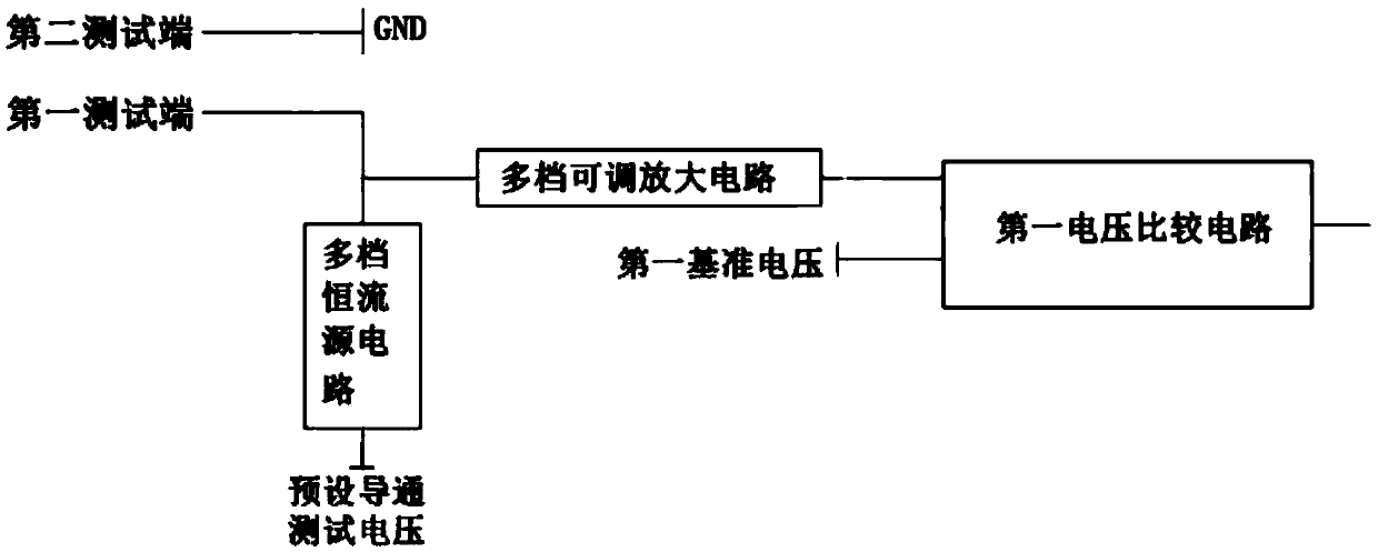
[0066] This embodiment provides a conduction test device. Various control signals and control commands in this embodiment are output by a host computer connected to the conduction test device, such as figure 1 As shown, it includes: a first test terminal, a second test terminal, a multi-level constant current source circuit, a multi-level adjustable amplifier circuit and a first voltage comparison circuit, wherein

[0067] The first test terminal is connected to one end of the multi-level constant current source circuit and the multi-level adjustable amplifier circuit;

[0068] The second test terminal is grounded, and the first test terminal and the second test terminal are used to respectively connect with two test points on the circuit board to be tested, so as to test whether the conduction between the two test points is qualified;

[0069] The other end of the multi-level constant current source circuit is connected to the preset conduction test voltage, which is used to ...

Embodiment 2

[0089] This embodiment provides an insulation testing device. Various control signals and control commands in this embodiment are output by a host computer connected to the insulation testing device, such as Figure 6 As shown, it includes: a third test terminal, a fourth test terminal, an operational amplifier circuit and a second voltage comparison circuit, wherein

[0090] The operational amplifier circuit includes a plurality of feedback circuits and an operational amplifier U17A, one end of the plurality of feedback circuits is respectively connected to the first input terminal of the operational amplifier U17A, and the other end is respectively connected to the output terminal of the operational amplifier U17A as the output terminal of the operational amplifier circuit, The second input terminal of the operational amplifier U17A is grounded;

[0091] Each of the plurality of feedback circuits includes a first feedback resistor and a controllable switch connected in serie...

Embodiment 3

[0099] Such as Figure 7 As shown, this embodiment provides a test system for a general test machine. Various control signals and control commands in this embodiment are output by the host computer connected to the test system, including multi-level constant current source circuits, multi-level An adjustable amplifier circuit, a first voltage comparison circuit, an operational amplifier circuit and a second voltage comparison circuit, a first controllable switch, and fifth and sixth test terminals, wherein


PUM


Abstract

The invention discloses a connection test device, an insulation test device and a test system of a universal test machine. The connection test device comprises a first test end, a second test end, a multi-range constant-current circuit, a multi-range adjustable amplification circuit and a first voltage comparison circuit, wherein the first test end is connected with one end of the multi-range constant-current circuit and one end of the multi-range adjustable amplification circuit; the second test end is grounded; the first test end and the second test end are respectively used for being connected with two points to be tested on a circuit board to be tested; the other end of the multi-range constant-current circuit is connected with preset connection test voltage; the other end of the multi-range adjustable amplification circuit is connected with the first voltage comparison circuit; the first voltage comparison circuit is used for comparing voltage output by the first voltage comparison circuit with first reference voltage; when the voltage is higher than the first reference voltage, failed connection between the two points to be tested is judged.

Description

technical field [0001] The invention relates to the field of PCB board testing, in particular to a test system of a conduction test device, an insulation test device and a universal test machine. Background technique [0002] With the continuous emergence of products using large-scale integrated circuits, the corresponding PCB installation and testing work has become more and more important. Universal testing of printed circuit boards is a traditional testing technique in the PCB industry. The earliest general-purpose electrical testing technology can be traced back to the late 1970s and early 1980s. Since the components at that time were all in standard packages (Pitch is 100mil), and the PCB only had the density level of THT (Through Hole Technology), European and American testing machines The manufacturer designed a testing machine with a standard grid. As long as the components and wiring on the PCB are arranged according to the standard distance, each test point will f...

Claims


Application Information

Patent Timeline
Patent Type & Authority Applications(China)
IPC IPC(8): G01R31/28
CPCG01R31/12G01R31/2806G01R31/2812G01R31/2818
Inventor 赵凌云
Owner JOINT STARS TECH
Why Eureka
Try Eureka