
Reset unit for correcting displacement of damper on electric transmission line

A technology of transmission lines and anti-vibration hammers, which is applied in the direction of overhead lines/cable equipment, etc., can solve the problems of clamp grip changes, maximum pressure, and inability to effectively compensate wire creep, etc., to achieve fast calibration process and improve calibration efficiency , the effect of good walking performance

Active Publication Date: 2016-04-20
STATE GRID CORP OF CHINA +1
View PDF7 Cites 13 Cited by
  • Summary
  • Abstract
  • Description
  • Claims
  • Application Information

AI Technical Summary

Problems solved by technology

[0004] One is that the grip strength of the anti-vibration hammer clamp cannot meet the needs of the line erection project
Second, the anti-loosening measures of the anti-vibration hammer clamp cannot effectively compensate for the creep of the wire
The third is that the construction personnel failed to reach the maximum pressure when tightening the bolts
Fourth, the design of the center of gravity of the two ears of the anti-vibration hammer is unreasonable and its own weight leads to a slip to the center of the gear during the vibration process.
Fifth, the initial elongation of the wire and the inconsistent thermal expansion coefficient of the wire and the anti-vibration hammer lead to changes in the grip of the wire clamp
[0007] However, the above improvement measures can only prevent the displacement of the anti-vibration hammer to a certain extent, but after the anti-vibration hammer is installed, in case of displacement, there is currently no effective means to assist the reset of the anti-vibration hammer

Method used


Image

  • Reset unit for correcting displacement of damper on electric transmission line
  • Reset unit for correcting displacement of damper on electric transmission line
  • Reset unit for correcting displacement of damper on electric transmission line

Examples


Embodiment Construction

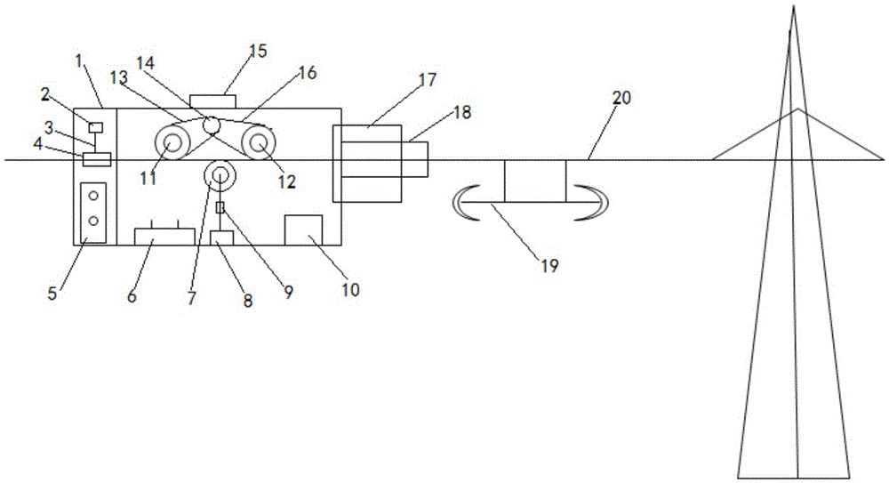
[0031] Aiming at the displacement of the anti-vibration hammer on the power transmission line due to various reasons, the present invention proposes a remote-controlled reset machine, which continuously strikes the side of the anti-vibration hammer in the form of impact, so that the anti-vibration hammer is continuously impacted. return to the original position. The details are as follows:

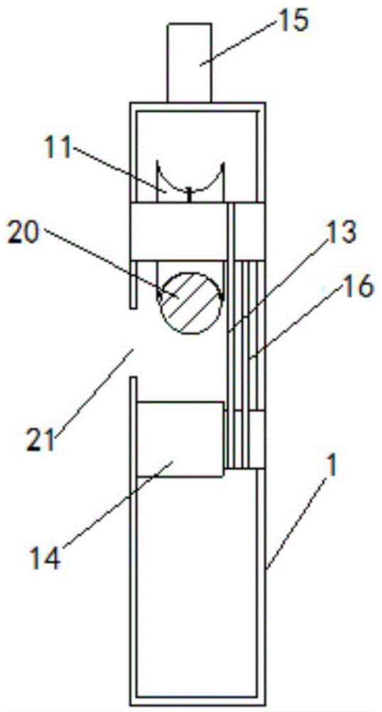
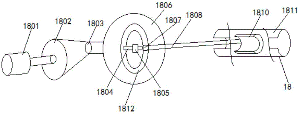
[0032] A resetting machine for correcting the displacement of an anti-vibration hammer of a power transmission line, comprising a housing 1, a laser range finder 17 and an impactor 18 are arranged at the front end of the housing 1, a strip-shaped opening 21 is opened on the housing 1 along the length direction, and the housing 1 1 is hung on the transmission line 20 through the strip-shaped opening 21, so that the transmission line 20 passes through the interior of the housing 1; a walking wheel is provided above the transmission line 20 inside the housing 1, and a wheel that can be moved ...


PUM


Abstract

The invention discloses a reset unit for correcting the displacement of a damper on an electric transmission line. The reset unit comprises a shell, wherein a laser range finder and a striker are arranged at the front end of the shell, a strip-shaped opening is formed in the shell in the length direction, and the shell is hung on a power transmission line through the strip-shaped opening to enable the power transmission line to pass through the interior of the shell; traveling wheels are arranged in the shell and located above the power transmission line, and a locking wheel capable of moving near the power transmission line is arranged in the shell and located below the power transmission line; a signal transceiver and a controller are also arranged inside the shell, the controller is connected with the signal transceiver, the laser range finder and the striker, movement of the shell and working of the striker are controlled by a remote controller matched with the signal transceiver, and the striker can reciprocate along the power transmission line to strike the damper constantly so as to make the damper reset. The whole reset unit is controlled remotely to move, correction and operation are easy, operability is high, and safety is high.

Description

【Technical field】 [0001] The invention relates to a reset device, in particular to a reset machine capable of correcting the displacement of an anti-vibration hammer of a power transmission line. 【Background technique】 [0002] There are many vibration damping devices selected in the power system, and a component installed on the wire designed to prevent breeze vibration is widely used in the actual erection of transmission lines. In principle, the anti-vibration hammer consists of a short steel strand with a heavy hammer installed at both ends, and a splint that can be hung on the wire is installed in the middle. When the wire vibrates, the steel strand of the anti-vibration hammer The two ends of the wire are constantly shaking up and down, so as to consume the vibration energy transmitted from the wire, thereby reducing the amplitude of the wire, so as to reduce the harm caused by the breeze vibration. [0003] After running for a period of time, the anti-vibration hamme...

Claims


Application Information

Patent Timeline
IPC IPC(8): H02G1/02
CPCH02G1/02
Inventor 董根岭黄琪伟董思思黄明亮罗万兴王刚峰贾林威王凛冯宇豪王峰任锦辉刘晓娟闫大海张邹林李曼娜李海李倩陆璐窦娟王刚赵兴耀程鹏姬鹏博王洋张波黄彬周筱强孟瑞刘万荣高占平毛智勇张宏伟李根党南好产陈边江刘辉王凯峰岳永超张涛冯栋潘晨郭洋段鹏缑俊席晨光周勇陈莉李新成
Owner STATE GRID CORP OF CHINA
Learn More