Instrument machine tool provided with infrared detection unit

An infrared detection and machine tool technology, which is used in manufacturing tools, measuring/indicating equipment, metal processing mechanical parts, etc., can solve the problems of difficult to guarantee processing consistency, equipment safety risks, equipment failures, etc. The effect of improving work safety and prolonging the service life

Active Publication Date: 2016-04-27
林宗升
View PDF6 Cites 4 Cited by
  • Summary
  • Abstract
  • Description
  • Claims
  • Application Information

AI Technical Summary

Problems solved by technology

The problems existing in the existing technology are: it is necessary to manually determine whether the tool is in place, and it is difficult to guarantee the consistency of processing; usually only one shape of the tool can be clamped at a time for processing, and the tool needs to be replaced manually repeatedly when performing mechanical processing with more complex shapes, which is time-consuming Laborious; at present, some instrument machine tools with infrared detection units with various tools have appeared on the market, but the tools are exposed relative to the cutter head, which poses safety risks to the equipment itself and operators; in addition, the existing CNC lathes Or there is no cooling mechanism at all or the setting of the cooling mechanism is unreasonable, which will easily lead to overheating and scrapping of the workpiece; moreover, the existing CNC lathes usually do not deal with cutting chips, which is easy to cause equipment failure due to cutting chips splashing into the joints of various functional components. big security risk

Method used


Image

  • Instrument machine tool provided with infrared detection unit

Examples


Embodiment Construction

[0017] Below in conjunction with specific embodiment and accompanying drawing, the present invention will be further described:

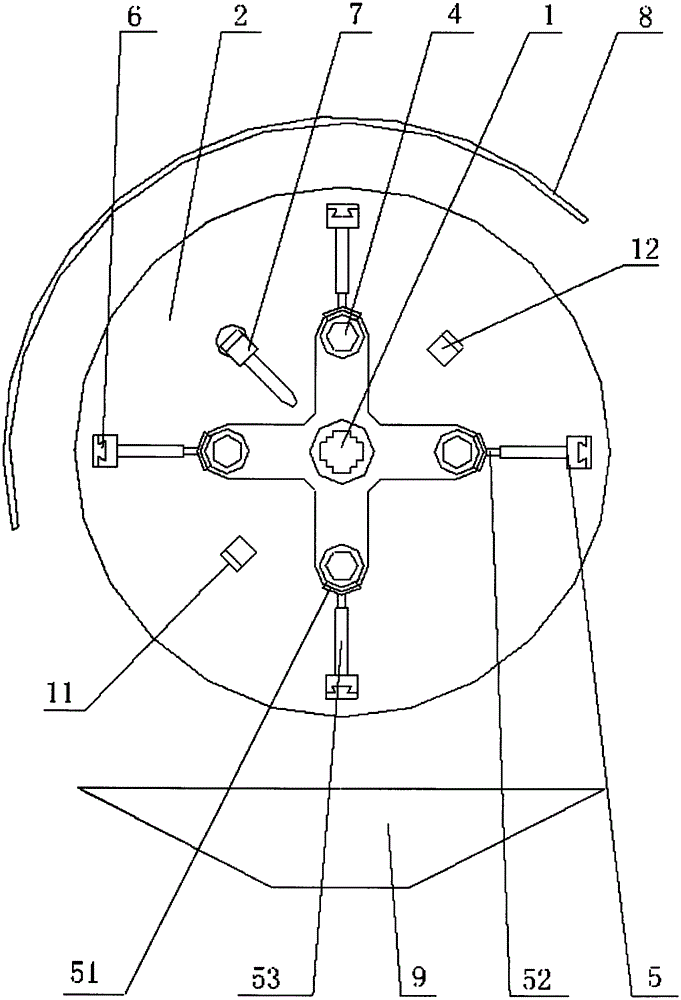
[0018] Refer to attached figure 1 As shown, the instrument machine tool with an infrared detection unit of the present invention includes a workpiece clamping mechanism and a tool clamping mechanism, the workpiece clamping mechanism is provided with a feed drive mechanism, the tool clamping mechanism is provided with a displacement drive mechanism, and the tool clamping mechanism An infrared emitter 11 and an infrared receiver 12 are arranged on both sides of the initial processing position. Both the infrared emitter 11 and the infrared receiver 12 are connected to a controller. An alarm device, at least one of the infrared transmitter 11 and the infrared receiver 12 is provided with an angle / position adjustment mechanism; the tool clamping mechanism includes a positioning shaft 1, and a tool disc 2 is set on the positioning shaft 1, and the tool di...


PUM


Abstract

The invention provides an instrument machine tool provided with an infrared detection unit. The instrument machine tool comprises a workpiece clamping mechanism and a tool clamping mechanism, wherein an infrared transmitter and an infrared receiver are arranged on two sides of the tool clamping mechanism; the tool clamping mechanism comprises a positioning shaft sleeved with a tool plate, at least two tool movement grooves are formed in the tool plate, and tools are arranged in the tool movement grooves in a penetrating manner; tool pushing mechanisms are arranged in the tool movement grooves and provided with tool locking / automatically unlocking mechanisms, tool returning mechanisms are arranged in the tool movement grooves, and the tool pushing mechanisms provided with sliding guide rail mechanisms and push sliding driving mechanisms; a tool capture mechanism is arranged on the positioning shaft. The instrument machine tool has the beneficial effects as follows: whether a tool is in place or not is detected automatically by the aid of infrared rays, and time and labor are saved; multiple groups of tools are arranged in the tool plate in a hidden manner and are safe to use, various actuating mechanisms for tool replacement are reasonably arranged, and the tool replacement action is stable and smooth.

Description

technical field [0001] The invention relates to the field of machining, in particular to an instrument machine tool with an infrared detection unit. Background technique [0002] Existing instrument machine tools with infrared detection units generally include a workpiece clamping mechanism and a tool clamping mechanism, the workpiece clamping mechanism is provided with a feed drive mechanism, and the tool clamping mechanism is provided with a displacement drive mechanism. The problems existing in the existing technology are: it is necessary to manually determine whether the tool is in place, and it is difficult to guarantee the consistency of processing; usually only one shape of the tool can be clamped at a time for processing, and the tool needs to be replaced manually repeatedly when performing mechanical processing with more complex shapes, which is time-consuming Laborious; at present, some instrument machine tools with infrared detection units with various tools have ...

Claims


Application Information

Patent Timeline
Patent Type & Authority Applications(China)
IPC IPC(8): B23Q1/01B23Q3/154B23Q11/00B23Q11/08B23Q11/10B23Q15/14B23Q17/00B23Q17/22B23Q17/24
CPCB23Q1/01B23Q3/1543B23Q3/1546B23Q11/0046B23Q11/08B23Q11/1038B23Q11/1061B23Q15/14B23Q17/003B23Q17/22B23Q17/2233B23Q17/249
Inventor 李亦琴
Owner 林宗升
Why Eureka
Try Eureka