Auxiliary heat pump device of water heater and control method

A technology of a heat pump device and a control method, which is applied in the field of heat pump devices and hot water heating control, can solve the problems of reducing air humidity, increasing air humidity in bathrooms, and increasing energy consumption, so as to reduce heat energy loss, save energy, reduce The effect of waiting time

Inactive Publication Date: 2016-04-27
QINGDAO ECONOMIC & TECHN DEV ZONE HAIER WATER HEATER
View PDF6 Cites 7 Cited by
  • Summary
  • Abstract
  • Description
  • Claims
  • Application Information

AI Technical Summary

Problems solved by technology

At the same time, a large amount of water vapor will be generated in the bathing process to diffuse into the bathing room, increasing the humidity of the air in the bathing roo

Method used


Image

  • Auxiliary heat pump device of water heater and control method
  • Auxiliary heat pump device of water heater and control method
  • Auxiliary heat pump device of water heater and control method

Examples


Embodiment 1

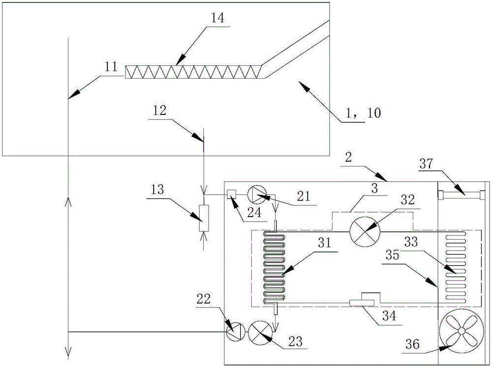
[0060] Such as figure 1 As shown, this embodiment introduces an auxiliary heat pump device for a water heater, and the heat pump device includes a heat pump system 3 . The heat pump system 3 is composed of a compressor 32 , a condenser 31 , an evaporator 33 and an expansion valve 34 sequentially connected through pipelines to form a circulation channel for refrigerant flow.

[0061] Such as Figure 5 As shown, in this embodiment, the condenser 31 is a sleeve condenser, and the sleeve condenser includes an outer tube 311 and an inner tube 312 sleeved in the outer tube. The channel between the outer tube 311 and the inner tube 312 is the first channel, and the channel in the inner tube 312 is the second channel. The first channel and the second channel are set relatively independently. The two ends of the first channel or the second channel are respectively provided with a water inlet 313 and a water outlet 314, the water inlet 313 is connected with the water inlet pipe 12 of...

Embodiment 2

[0065] Such as figure 1 As shown, in this embodiment, the water inlet or outlet of the condenser 31 is provided with a control device for controlling the flow of circulating water between the water heater and the condenser, so as to realize the circulation between the water tank 10 of the water heater 1 and the condenser 31 Water flow control.

[0066] The control device at least includes a water pump 23 that provides water flow power to form a circulating water flow between the water tank 10 and the condenser 31; preferably, the water pump 23 is arranged on the connecting pipeline between the condenser 31 and the water outlet pipe 11 . It is also possible to arrange the water pump 23 on the connecting pipeline between the condenser 31 and the water inlet pipe 12 (not indicated in the drawings).

[0067] The control device also includes a one-way valve for controlling the on-off of the pipeline, and the one-way valve is arranged on the circulating water flow channel formed b...

Embodiment 3

[0070] Such as figure 1 As shown, in this embodiment, the auxiliary heat pump device includes a casing 2 , and the heat pump system 3 is arranged in a chamber surrounded by the casing 2 . The water inlet end and the water outlet end of the condenser 31 of the heat pump system 3 are respectively arranged outside the casing 2 to form the water inlet end and the water outlet end of the auxiliary heat pump device. Both ends of the air duct 35 of the heat pump system 3 are located outside the casing 2 or provided at corresponding openings of the casing 2 to form an air inlet and an air outlet of the auxiliary heat pump device.


PUM


Abstract

The invention relates to an auxiliary heat pump device of a water heater and a control method. The heat pump device comprises a heat pump system. The heat pump system comprises a condenser, a compressor, an evaporator, an expansion valve and an air supply device, wherein the condenser is provided with a water inlet end communicating with a water inlet pipe of the water heater, and a water outlet end communicating with a water outlet pipe of the water heater, so that circulating water flow between the water heater and the condenser is formed, and the purpose of auxiliary heating of the circulating water flow through heat in air by the heat pump system is achieved. More specifically, the evaporator is arranged close to the position where a user uses hot water of the water heater, so that the evaporator collects waste heat, diffused to the environment, of the hot water of the water heater and transfers the collected waste heat through refrigerants, heat exchange between the circulating water flow flowing through the condenser and the refrigerants flowing through the condenser is achieved, and auxiliary heating treatment of water in the water heater through the heat pump system is achieved.

Description

technical field [0001] The present invention relates to the field of water heaters, in particular to an external heat pump device providing auxiliary heating for the water heater, and also relates to a hot water heating control method for the water heater equipped with the auxiliary heat pump device. Background technique [0002] Existing water heaters can be divided into electric heating tube type, solar heating type, heat pump type, gas or / natural gas type according to different heating methods. However, no matter what kind of heating method the water heater is used for a certain period of time, there will be large energy consumption, low utilization rate of natural energy, and aging heating elements, resulting in reduced heating efficiency of the water heater and delayed hot water outlet time. [0003] Therefore, it becomes a new research topic to provide a kind of auxiliary heating device, after directly refitting the existing water heater, the heating equipment that can...

Claims


Application Information

Patent Timeline
IPC IPC(8): F24H4/02F24H9/20
Inventor 周浩王慧杨磊陈康姜慧峰
Owner QINGDAO ECONOMIC & TECHN DEV ZONE HAIER WATER HEATER
Why Eureka
Try Eureka