
A laser distance measuring device

A technology of laser distance measurement and laser, which is applied in the direction of measuring devices, radio wave measuring systems, electromagnetic wave reradiation, etc., can solve the problems of many measuring personnel, low safety factor, large measurement error, etc., and achieve safe data communication and aiming accuracy High and prolong service life effect

Inactive Publication Date: 2017-08-25
SICHUAN HONGGUANG AUTO MACHINERY ELECTRONICS
View PDF7 Cites 0 Cited by
  • Summary
  • Abstract
  • Description
  • Claims
  • Application Information

AI Technical Summary

Problems solved by technology

The traditional measurement method uses the theodolite to measure the sight scale and then uses the distance measurement tool to measure. It requires many surveyors and requires high professionalism of the surveyors; it has great restrictions on the terrain and environment of the survey. Under unconventional terrain and harsh environmental conditions The measurement cannot be completed; the distance between two points cannot be measured directly during the measurement. It is necessary to calibrate the aiming and then measure, so the reaction time of the measurement is long and the measurement error is large. The safety factor is low in working areas such as high-rise buildings and high-traffic roads. , cannot fully adapt to the current fast, efficient, accurate and safe requirements

Method used


Image

  • A laser distance measuring device
  • A laser distance measuring device
  • A laser distance measuring device

Examples


Embodiment Construction

[0026] The present invention will be further described below in conjunction with the accompanying drawings, but the protection scope of the present invention is not limited to the following description.

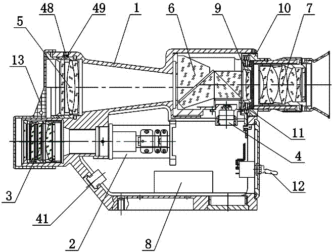
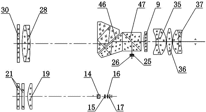
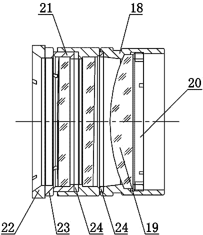
[0027] Such as figure 1 As shown, a laser distance measuring device includes a measurement and control box 1, a laser 2, a transmitting optical system 3, a receiver 4, a receiving objective lens system 5, a combined prism 6, an eyepiece system 7 and a circuit board 8, and the laser 2 is fixed on the measurement and control Inside the box 1, the laser 2 is connected to the laser power supply, the emission optical system 3 is fixed on the lower front side of the measurement and control box 1, and the emission optical system 3 is horizontally aligned with the axis of the laser 2, and the receiving objective lens system 5 is installed on the front side of the measurement and control box 1 In the upper part, the rear side of the receiving objective lens system 5 is sequentially pr...


PUM


Abstract

The invention relates to a laser ranging device, comprising a measurement and control box, a laser, a transmitting optics system, a receiver, a receiving objective lens system, a combined prism, an ocular lens system, and a circuit board. The laser is fixedly arranged in the measurement and control box. The transmitting optics system is fixed at the lower part of the front side of the measurement and control box and is in horizontal alignment with the axis of the laser. The receiving objective lens system is installed at the upper part of the front side of the measurement and control box. The combined prism and the ocular lens system are successively arranged at the rear side of the receiving objective lens system. The combined prism is fixed inside the measurement and control box. The ocular lens system is fixed at the upper part of the rear side of the measurement and control box through an ocular lens connecting base. The axes of the receiving objective lens system, the combined prism and the ocular lens system are horizontally aligned. A reticule is arranged between the combined prism and the ocular lens system. The receiver is arranged under the combined prism. The circuit board is arranged at the bottom of the interior of the measurement and control box and is connected to the laser and the receiver. The laser ranging device is advantageous in that, by use of the device, middle and short distance can be quickly, accurately and safely measured and real-time data communication can be realized.

Description

technical field [0001] The invention relates to a distance measuring device, in particular to a laser distance measuring device. Background technique [0002] Under the background of today's era, the construction of roads, bridges, and even the construction and operation of overhead transmission lines use advanced laser range finders, which can bring great speed and convenience to the work. How to provide a laser distance measuring device for measurement, accurately utilize the advantages of laser distance measurement, and guide production in construction and operation and maintenance are practical problems that need to be solved at present. The traditional measurement method uses the theodolite to measure the sight scale and then uses the distance measurement tool to measure. It requires many surveyors and requires high professionalism of the surveyors; it has great restrictions on the terrain and environment of the survey. Under unconventional terrain and harsh environment...

Claims


Application Information

Patent Timeline
Patent Type & Authority Patents(China)
IPC IPC(8): G01S17/08
CPCG01S17/08
Inventor 张龙张志刚彭涛武邓斌王滨李文柱李长安舒旭东
Owner SICHUAN HONGGUANG AUTO MACHINERY ELECTRONICS
Learn More