Voltage peak control circuit applied to DC-DC converter

A DC-DC, voltage peak technology, applied in the control/regulation system, DC power input conversion to DC power output, instruments, etc., can solve the problems of serious electromagnetic interference, long adjustment time, slow dynamic response, etc., to achieve voltage dynamics The effect of good characteristics, simple and clear structure, and fast response speed

Inactive Publication Date: 2016-04-27
ZHEJIANG UNIV
View PDF3 Cites 4 Cited by
  • Summary
  • Abstract
  • Description
  • Claims
  • Application Information

AI Technical Summary

Problems solved by technology

[0003] In the control of DC-DC converters, if a simple open-loop control is used, there will be problems such as low output accuracy, long adjustment time, and slow dynamic response. Therefore, closed-loop feedback control must be used. Currently, the closed-loop control method mainly includes voltage feedback. PID control, hysteresis control, current peak control, etc.
Voltage feedback PID control requires accurate modeling of the converter, and it is cumbersome to design reasonable and optimal PID parameters; hysteresis control mainly uses the voltage or current in the circuit to track a given voltage and current hysteresis range, and the switching tube The frequency is not fixed, it is greatly affected by the load, the filter design is difficult, and the electromagnetic interference problem is serious; the current peak control has a certain current limiting protection function, which improves reliability, but the current peak control is very sensitive to circuit noise, and there is no The output voltage is directly controlled, so the dynamic characteristics of the output voltage are not good

Method used


Image

  • Voltage peak control circuit applied to DC-DC converter
  • Voltage peak control circuit applied to DC-DC converter
  • Voltage peak control circuit applied to DC-DC converter

Examples


Embodiment Construction

[0017] The present invention will be further described below in conjunction with the accompanying drawings.

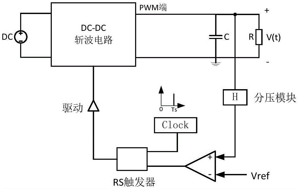
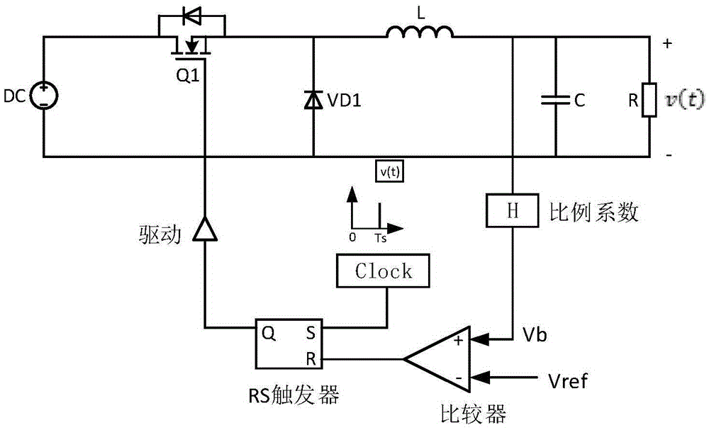
[0018] figure 1 It is a schematic diagram of the voltage peak control circuit applied to the DC-DC chopper circuit, taking the Buck chopper circuit as an example, the voltage peak control circuit applied to the Buck circuit, such as figure 2 As shown, it includes a DC power supply DC, a MOSFET switch tube Q1 with an anti-parallel diode, a diode VD1, an inductor L, a capacitor C, and a load resistor R to form the main power circuit; and A proportional link (generally obtained by dividing voltage by resistors, that is, a voltage dividing module), a comparator, an RS flip-flop, a clock module, and a driving module constitute a voltage peak control loop. The main power circuit Buck realizes the function of step-down, and the input-output voltage relationship in the steady state of continuous operation (CCM) mode is:

[0019] V ...


PUM


Abstract

The invention discloses a voltage peak control circuit applied to a DC-DC converter. The voltage peak control circuit comprises a DC power supply, a DC-DC chopper circuit, a filter capacitor, an RS trigger, a clock module, a drive module, a comparator and a voltage division module, wherein the circuit is a closed-loop control scheme; an output voltage is compared with a given reference by detecting the output voltage; and on or off of a switch tube in the DC-DC chopper circuit is controlled by the RS trigger, so that control on the voltage peak is achieved. The voltage peak control circuit disclosed by the invention is simple and clear in structure and convenient to control; compared with a PID control, a complicated parameter calculation process is not needed; the dynamic characteristics of the voltage are good; the response speed is high; the regulating time is short; and in addition, the voltage peak control circuit also has an overvoltage protection function.

Description

technical field [0001] The invention belongs to the technical field of power electronics and relates to a voltage peak control circuit, in particular to a voltage peak control circuit applied to a DC-DC converter. Background technique [0002] A DC-DC converter (DC-DC converter for short) is a power electronic circuit topology that converts direct current at a voltage level into direct current at other voltage levels. DC power supply has a very wide range of application markets and application fields. The current DC-DC converter mainly has the following main topologies: Buck circuit——a step-down chopper, whose output average voltage U0 is smaller than the input voltage Ui, with the same polarity; Boost circuit——a step-up chopper, whose The average output voltage U0 is greater than the input voltage Ui, and the polarity is the same; Buck-Boost circuit - step-down or step-up chopper, the average output voltage U0 is greater than or less than the input voltage Ui, and the pola...

Claims


Application Information

Patent Timeline
Patent Type & Authority Applications(China)
IPC IPC(8): H02M3/157H02M1/32
CPCH02M1/32H02M3/157H02M1/0012
Inventor 常晓飞杨雁勇
Owner ZHEJIANG UNIV
Why Eureka
Try Eureka