Heat dissipation structure of computed tomography (CT) device

A heat dissipation structure and equipment technology, applied in X-ray equipment, radiological diagnostic equipment, medical science, etc., can solve the problems of large and clumsy CT equipment, increase the height of the frame shell, and reduce the heat dissipation performance, etc., to achieve Avoid floating around, reduce installation size, and improve heat dissipation efficiency

Active Publication Date: 2016-04-27
SHANGHAI UNITED IMAGING HEALTHCARE
View PDF12 Cites 9 Cited by
  • Summary
  • Abstract
  • Description
  • Claims
  • Application Information

AI Technical Summary

Problems solved by technology

However, this setting method has three obvious disadvantages: 1. The fan installed above the heating component will significantly increase the height of the rack shell, making the overall size of the CT equipment appear large and clumsy; 2. Due to the fact that the fan installed above the heating component Too close to the rotating part of the heating component, resulting

Method used


Image

  • Heat dissipation structure of computed tomography (CT) device
  • Heat dissipation structure of computed tomography (CT) device
  • Heat dissipation structure of computed tomography (CT) device

Examples


Embodiment 1

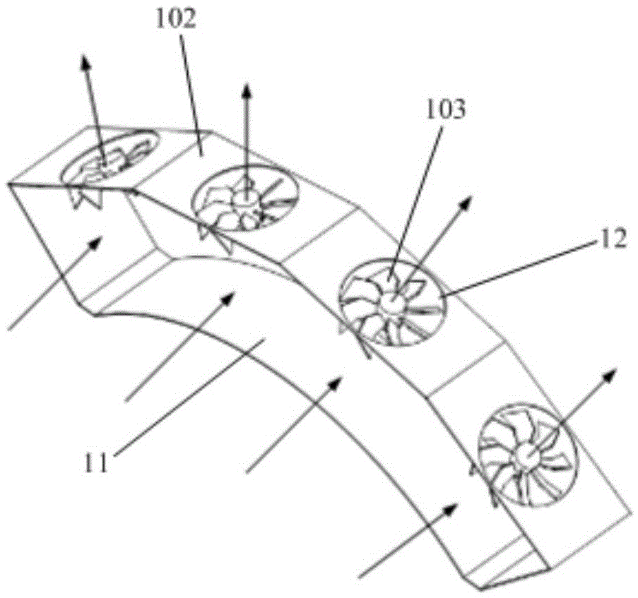
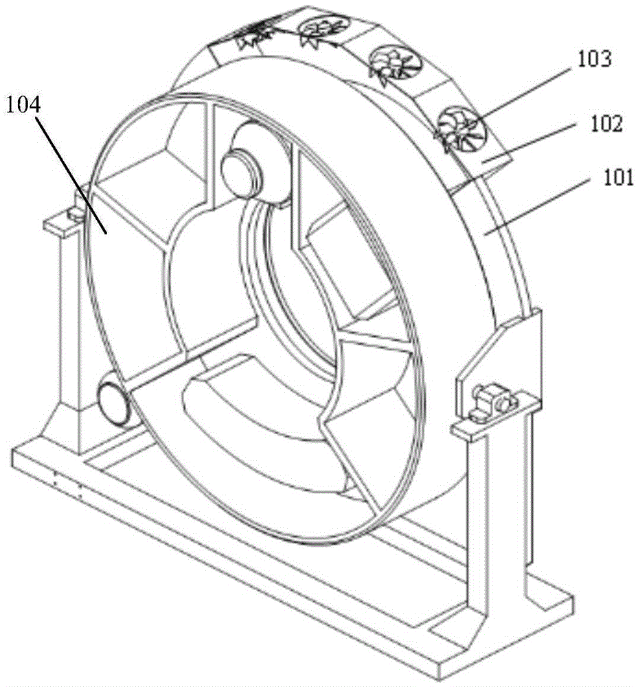
[0042] like Figures 1 to 3 As shown, in an embodiment of the present invention, the entire surface of the air duct 102 close to the front side of the support plate 101 is the air inlet 11, and the upper surface of the air duct 102 is provided with at least For one of the air outlets 12, the number of the fans 103 is the same as the number of the air outlets 12, and they are respectively arranged in the corresponding air outlets 12, and the other surfaces of the air duct 102 are closed surfaces. The integrated wide air inlet design of the air duct 102 significantly reduces the air inlet wind resistance, greatly improves the heat dissipation efficiency of the fan 103, and at the same time significantly reduces the working noise. Therefore, the air in the air duct 102 will not be disturbed, so that the heat dissipation effect of the heat dissipation structure of the CT equipment will not be affected.

[0043] Further, the shape of the air outlet 12 is a circle matching the shap...

Embodiment 2

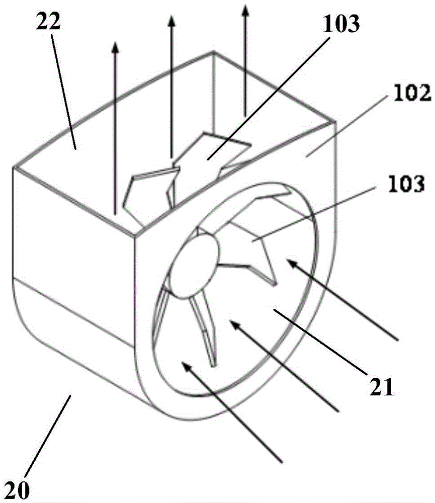
[0046] like Figures 4 to 6 As shown, in another embodiment of the present invention, the air duct 102 includes at least one independent air duct unit 20, and the at least one air duct unit 20 is located on the rear side of the support plate 101. The air inlet 21 is opened on one surface of the air duct unit 20 close to the support plate 101 . In the air inlet 21, the support plate 101 is provided with a corresponding opening 10 near the air inlet 21, and the entire upper surface of the air duct unit 20 is the air outlet 22. The air duct unit The remaining faces of 20 are closed faces. The independent air duct design of the air duct unit 20 can further avoid the mutual influence between the fans 103, so as not to affect the heat dissipation effect of the heat dissipation structure of the CT equipment.

[0047] Further, the shape of the air inlet 21 is a circle that matches the shape of the fan 103 , so that the exhaust efficiency of the fan 103 can be improved.

[0048] Fur...


PUM


Abstract

The invention provides a heat dissipation structure of a computed tomography (CT) device. Due to the structural design of an air duct and fans, fans do not interfere with each other. The fans and the air duct are fixed on a support plate, the rear space of the support plate is fully used, and the fans and the air duct are not directly installed over a heat dissipation component, so that the installation size above a CT device rack can be effectively reduced, and the overall height of the rack is lowered. Due to cooperation of the air duct and the support plate, the impact of the fans on the air of the rear space of the support plate is effectively prevented, independence of the front space and the rear space of the support plate is realized, worn scraps of a transmitting belt at the rear side of the support plate and carbon powder on a slide ring carbon brush are prevented from blowing up and flying around so as not to pollute the whole rack system, the rotation noise of a rotation component at the front side of the support plate is lowered, and the heat dissipation efficiency is improved. Through adoption of the structural design of the air duct, inlet air resistance in the heat dissipation structure can be reduced obviously, the heat dissipation efficiency of the heat dissipation structure is greatly improved, and the working noise of the heat dissipation structure is lowered remarkably.

Description

technical field [0001] The invention relates to the field of medical equipment design, in particular to a heat dissipation structure of CT equipment. Background technique [0002] The heat dissipation of the CT (Computed Tomography) machine rack is directly related to the stability of the detector and the image quality. Therefore, the heat dissipation effect of the CT equipment rack has become an important factor for testing the quality of the CT equipment. Generally, the heat dissipation of the CT equipment rack is carried out by the heat dissipation structure of the CT equipment, and the heat dissipation performance of the heat dissipation structure is heavily dependent on the arrangement position of the fan and the design of the air duct. [0003] At present, most of the fans in the heat dissipation structure of CT equipment use axial flow fans, which are arranged above the heating components located on the front side of the support plate. The main heat source of the rack...

Claims


Application Information

Patent Timeline
IPC IPC(8): H05G1/02A61B6/00
CPCA61B6/4488H05G1/025
Inventor 叶婷缪俊杰
Owner SHANGHAI UNITED IMAGING HEALTHCARE
Why Eureka
Try Eureka