Electric floor wiping machine

A mopping machine and electric technology, applied in the field of ground cleaning, can solve the problems of inability to remove the dirt of mopping cloth at any time, reducing the working efficiency of mopping mop, complicated structure of mopping mop, etc., so as to achieve good mopping effect and simple structure. , the effect of improving efficiency

Active Publication Date: 2016-05-04
黑龙江省高杰环保科技发展有限公司
View PDF7 Cites 8 Cited by
  • Summary
  • Abstract
  • Description
  • Claims
  • Application Information

AI Technical Summary

Problems solved by technology

[0003] The object of the present invention is to provide an electric mopping machine to solve the problem that the existing mopping machine has a complex structure and cannot remove the dirt on the mopping cloth at any time. The problem of working efficiency of the machine

Method used


Image

  • Electric floor wiping machine
  • Electric floor wiping machine
  • Electric floor wiping machine

Examples


specific Embodiment approach 1

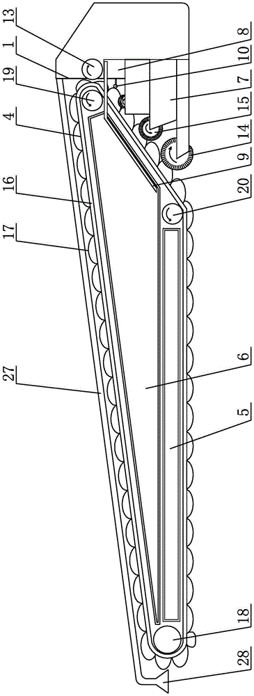
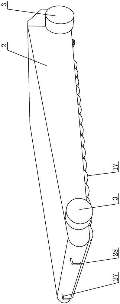
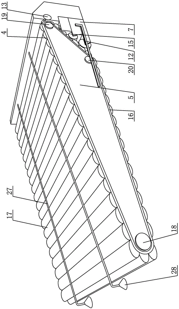
[0028] Specific implementation mode one: as Figure 1 ~ Figure 3 and Figure 7 ~ Figure 11 As shown, what is described in this embodiment is an electric mopping machine, which includes a frame 1, a housing 2 and four walking wheels 3 with built-in motors. The housing 2 is covered on the frame 1 and two The left and right sides of the front end of the frame 1 and the left and right sides of the rear end are respectively equipped with a walking wheel 3 with a built-in motor. The electric mopping machine also includes an electric mopping mechanism 4, a sewage tank 5, a clear water Case 6, dirt collection box 7, water pump 8, water inlet pipe 9, water spray pipe 10, connecting pipe 11, sewage pipe 12, extrusion roller motor 13, cleaning brush 14 and a plurality of cleaning roller motors 15;

[0029]The electric mopping mechanism 4 includes an endless belt 16, a mopping cloth or a collodion layer 17, a front roller motor 18, a rear roller motor 19 and an intermediate transition ro...

specific Embodiment approach 2

[0036] Specific implementation mode two: as figure 1 , image 3 , Figure 7 , Figure 8 and Figure 10 As shown, in the electric mopping machine described in Embodiment 1, the mopping cloth 17 is a microfiber cloth, which has a good water absorption effect, so that the mopping cloth 17 wipes the ground cleaner.

specific Embodiment approach 3

[0037] Specific implementation mode three: as Figure 9 As shown, in the electric mopping machine described in Embodiment 1, the outer peripheral surfaces of the front roller motor 18, the rear roller motor 19 and the intermediate transition roller motor 20 are all processed with a plurality of trapezoidal shapes along their respective circumferential directions. Tooth groove 22, the inner surface of the endless belt 16 is provided with a plurality of trapezoidal teeth 23 along the ring direction, the plurality of trapezoidal teeth 23 are arranged side by side along the width direction of the endless belt 16, all the trapezoidal teeth 23 of the endless belt 16 All cooperate one by one with a plurality of trapezoidal tooth slots 22 on the front roller motor 18, the rear roller motor 19 and the intermediate transition roller motor 20, which can prevent the endless belt 16 from slipping and make the overall transmission of the electric mopping machine more stable.


PUM


Abstract

The invention provides an electric floor wiping machine, and belongs to the technical field of floor cleaning. An annular belt is driven by a front roller motor, a rear roller motor and a middle transition roller motor to rotate, a floor wiping cloth or a collodion cotton layer is detachably connected to the outer surface of the annular belt, and a clear water tank, a sewage tank and a dirt collection tank are arranged in a rack; a water pump is communicated with the clear water tank through a water inlet pipe, an extrusion roller motor and the rear roller motor are used for extruding the floor wiping cloth or the collodion cotton layer, the water pump is communicated with a water spray pipe through a connecting pipe, multiple roller motors for removing dirt are all arranged between the front portion of the dirt collection tank and the floor wiping cloth or the collodion cotton layer, dirt removing brushes are fixed on the external circumferential surface of each roller motor for removing the dirt, dirt removing teeth are arranged on the end face of the front side wall of the dirt collection tank, the dirt removing brushes make close contact with the floor wiping cloth or the collodion cotton layer, and the dirt removing brushes are combed through the dirt removing teeth on the dirt collection tank which is communicated with the sewage tank through a sewage pipe. The electric floor wiping machine is used for wiping a floor, the floor wiping cloth or the collodion cotton layer can be cleaned at any time, and the working efficiency is improved.

Description

technical field [0001] The invention belongs to the technical field of floor cleaning, in particular to an electric floor mopping machine. Background technique [0002] Whether it is at home or in public places, wiping the ground is a kind of heavy physical labor. In order to enable people to be freed from heavy physical labor, there have been many types of mopping machines on the market. However, most of the mopping machines have complex structures, and the dirt on the mopping cloth cannot be removed at any time. The mopping cloth needs to be cleaned manually, which is time-consuming and laborious, and reduces the working efficiency of the mopping machine. Contents of the invention [0003] The purpose of the present invention is to provide an electric mopping machine to solve the problem that the existing mopping machine has a complex structure and cannot remove the dirt on the mopping cloth at any time. machine efficiency issues. [0004] For realizing the above obje...

Claims


Application Information

Patent Timeline
Patent Type & Authority Applications(China)
IPC IPC(8): A47L11/29A47L11/40
CPCA47L11/29A47L11/4013A47L11/4072A47L11/4088
Inventor 高翔
Owner 黑龙江省高杰环保科技发展有限公司
Why Eureka
Try Eureka