Sludge slurrying machine

A sludge slurry and sludge technology, applied in sludge treatment, water/sludge/sewage treatment, mixers, etc., can solve the problems of easily damaged paddles, decreased mixing effect, and complicated sludge properties, and achieve Guarantee stable operation, increase shear force, and improve pulping effect

Inactive Publication Date: 2016-05-04
CSD BEIJING E P DEV CO LTD
View PDF3 Cites 2 Cited by
  • Summary
  • Abstract
  • Description
  • Claims
  • Application Information

AI Technical Summary

Problems solved by technology

[0006] (1) Due to the complex nature of the sludge, it will contain some fibrous impurities, which are entangled on the shaft and blades of the vertical axis agitator, and the accumulation of time will cause the decline of the stirring effect and affect the normal use
[0007] (2) When bricks, small stones, iron blocks and other hard debris enter, it is very easy to damage the blade, and the replacement and maintenance procedures of the blade are more complicated
Since the dewatered sludge has basically no fluidity, it is difficult to clean and empty;
[0009] (4) Affected by the structure of the vertical mixing tank, sludge and diluent are added from the top and flow out from the bottom, which is suitable for sequential batch production. When continuous production is carried out, it is difficult to control the amount of material and the effect of pulping
The sequential batch production increases the number of equipment and the difficulty of control, requiring frequent switching of equipment
[0010] Based on the shortcomings of the above-mentioned existing technologies, it is necessary to develop a new type of sludge slurry equipment that can solve the problems of equipment winding, blockage, difficult emptying and operation control

Method used


Image

  • Sludge slurrying machine
  • Sludge slurrying machine
  • Sludge slurrying machine

Examples


Embodiment Construction

[0031] The objects and functions of the present invention and methods for achieving the objects and functions will be clarified by referring to the exemplary embodiments. However, the present invention is not limited to the exemplary embodiments disclosed below; it can be implemented in various forms. The essence of the description is only to help those skilled in the relevant art comprehensively understand the specific details of the present invention.

[0032] Hereinafter, embodiments of the present invention will be described with reference to the accompanying drawings. In the drawings, the same reference numerals represent the same or similar components, or the same or similar steps.

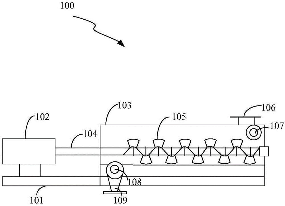
[0033] The invention provides a sludge pulping machine, such as figure 1 As shown, the sludge slurry machine includes: a transmission device 102, a transmission shaft 104, a paddle 105, a casing 103 and a base 101:

[0034] The transmission device 102 and the housing 103 are installed on ...


PUM

PropertyMeasurementUnit
widthaaaaaaaaaa

Abstract

The invention provides a sludge slurrying machine. The sludge slurrying machine comprises a transmission device, a transmission shaft, paddles, a casing and a base, wherein the transmission device and the casing are mounted on the base; the transmission device is connected with the transmission shaft and used for driving the transmission shaft to rotate; one end of the transmission shaft is connected with the transmission device, and the other end extends into the casing and is provided with the paddles; the paddles and the transmission shaft are set to form angles and are used for stirring and conveying sludge; a sludge addition port is formed in the upper end of the casing and used for addition of dewatered sludge to the casing; a discharging end is arranged at the bottom end of the casing and used for outputting a mixed and slurried material out of the sludge slurrying machine; the base is connected with the casing and used for supporting the sludge slurrying machine.

Description

technical field [0001] The invention relates to the field of municipal sludge treatment, and more specifically relates to a sludge pulping machine. Background technique [0002] Affected by the national environmental protection policy, the requirements for the treatment and disposal of sludge in municipal sewage treatment plants are becoming increasingly stringent. Anaerobic digestion is a treatment technology that can achieve sludge reduction, stabilization, harmlessness, and resource utilization. It is suitable for large-scale Promote projects that are large in size, have high sludge organic matter content, or require centralized treatment and disposal. [0003] When the sludge treatment and disposal plant conducts anaerobic digestion project construction, the moisture content of the sludge received from the external factory is generally about 80%, which cannot be directly anaerobic digestion, and water or thin sludge (with a moisture content of 97%-99% ) to dilute, adjus...

Claims


Application Information

Patent Timeline
Patent Type & Authority Applications(China)
IPC IPC(8): B01F7/04B01F15/02C02F11/00
CPCC02F11/00B01F27/2322B01F27/702B01F27/191B01F35/75
Inventor 杨永凯裴敏岳磊王丽涂飞彪
Owner CSD BEIJING E P DEV CO LTD
Why Eureka
Try Eureka