
Method for forming irregularly-shaped steel wire with S-shaped cross section

A forming method and cross-section technology, applied in metal rolling and other directions, can solve the problems of inability to achieve comprehensive performance indicators of flexible composite hoses, high cost, easy damage to molds, etc., and achieve excellent comprehensive performance indicators, high production efficiency, and fewer processes. Effect

Inactive Publication Date: 2016-05-04
中钢集团郑州金属制品研究院股份有限公司
View PDF5 Cites 3 Cited by
  • Summary
  • Abstract
  • Description
  • Claims
  • Application Information

AI Technical Summary

Problems solved by technology

The traditional S-shaped cross-section special-shaped steel wire solid-die drawing forming method is easy to damage the mold due to work hardening, and the cost is high, and the trial production period is long. The forming process of the S-section special-shaped steel wire proposed in "is too complicated, and there are many pass types to be processed, and the cost is too high. In addition, the comprehensive performance indicators required by the S-section special-shaped steel wire for flexible composite hoses cannot be achieved.

Method used

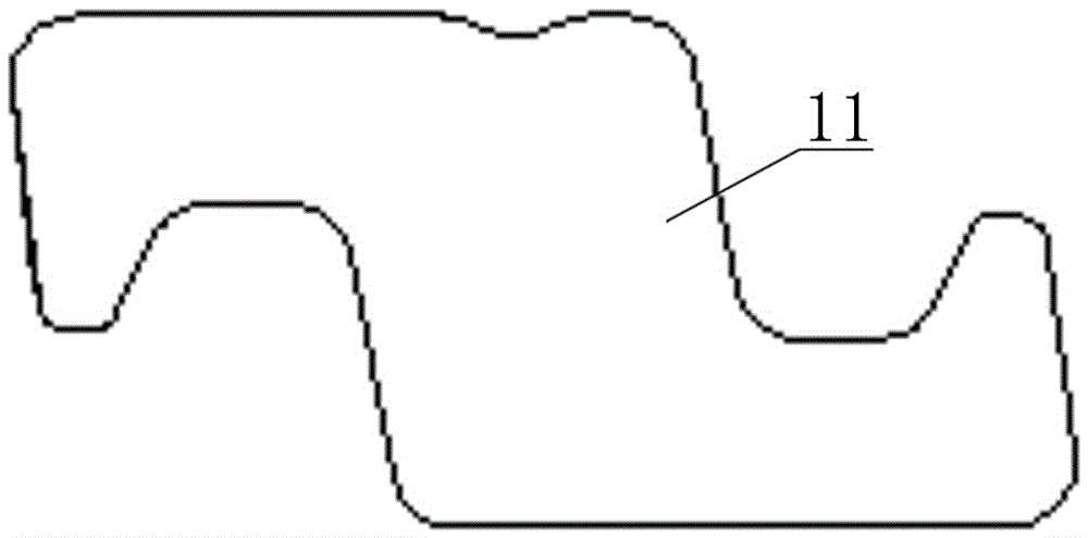

Image

  • Method for forming irregularly-shaped steel wire with S-shaped cross section
  • Method for forming irregularly-shaped steel wire with S-shaped cross section
  • Method for forming irregularly-shaped steel wire with S-shaped cross section

Examples


Embodiment Construction

[0027] The present invention will be further described below in conjunction with embodiment (accompanying drawing):

[0028] Such as figure 2 Shown, the molding method of S-shaped cross-section special-shaped steel wire of the present invention comprises the following steps:

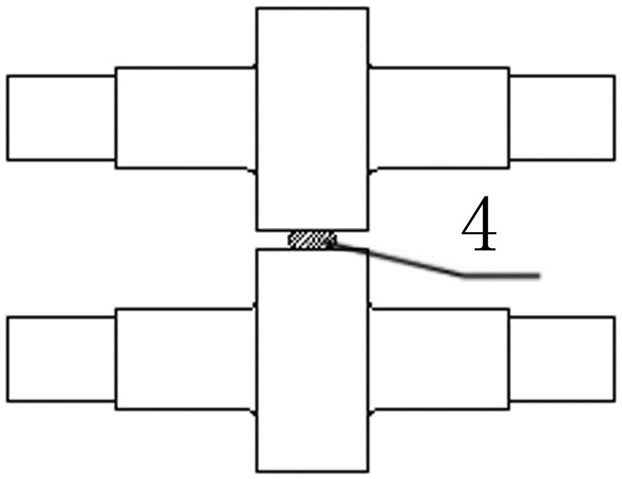
[0029] a. Using the qualified round steel wire 2 unscrewed from the pay-off I-shaped wheel 1 and having a cross-sectional area close to the finished product of the S-shaped cross-section special-shaped steel wire as a raw material, the upper and lower rollers of the first rolling mill 3 are pre-rolled to be parallel to the upper and lower sides First flat wire 4 (see image 3 );

[0030] b, passing the first flat steel wire 4 obtained in step a through the induction coil 5 arranged in front of the entrance of the second rolling mill 6 to be heated, and then entering the upper and lower rolls of the second rolling mill 6 to be rolled into an upper and lower diagonal initial Grooved second flat wire 7 ...


PUM

PropertyMeasurementUnit
hardnessaaaaaaaaaa
yield strengthaaaaaaaaaa
tensile strengthaaaaaaaaaa

Abstract

The invention discloses a method for forming an irregularly-shaped steel wire with an S-shaped cross section. The method comprises the following steps: a, taking a round steel wire as a raw material, primarily rolling the round steel wire into a first flat steel wire with parallel upper and lower upper surfaces by using upper and lower rollers of a first rolling machine; b, threading the first flat steel wire into a sensing ring for heating in front of an inlet end of a second rolling machine, and subsequently rolling the flat steel wire into a second flat steel wire with a trench in an opposite angle of the upper surface and the lower surface by using the upper and lower rollers of the second rolling machine; c, after cooling the second flat steel wire, further rolling the cooled second flat steel wire by using the upper, lower, left and right rollers of a third rolling machine, and obtaining a third flat steel wire with a cross section having the shape and the size approximate to those of an irregularly-shaped steel wire finished product with a S-shaped cross section; d, finely trimming and shaping the third flat steel wire by using the upper, lower, left and right rollers of a rolling mold, and obtaining the irregularly-shaped steel wire finished product with the S-shaped cross section. Due to multiple continuous rolling procedures of hot rolling first and cooling rolling later, the irregularly-shaped steel wire with the S-shaped cross section, which is excellent in comprehensive property indexes, can meet the use requirements of a flexible compound hose anti-pressure armor layer, and is small in amount of procedures, low in cost and high in production efficiency, can be formed.

Description

technical field [0001] The invention relates to a forming method of an S-shaped cross-section special-shaped steel wire. The S-shaped cross-section special-shaped steel wire produced by the forming method of the invention is suitable for the pressure-resistant armor layer of flexible pipes transported in offshore oil and gas fields. Background technique [0002] Traditional marine pipelines are mainly made of steel pipes, and the overall construction, installation and subsequent maintenance period is long and expensive. In recent years, flexible composite hoses that have emerged abroad have been gradually used in submarine oil, gas and water pipelines due to their advantages such as good corrosion resistance, strong adaptability to seabed topography, fast laying speed, low cost, and reusability. . Flexible composite hoses are divided into adhesive composite hoses and non-adhesive composite hoses. Adhesive composite hose is extruded into one by the polymer layer and the met...

Claims


Application Information

Patent Timeline
Patent Type & Authority Applications(China)
IPC IPC(8): B21B1/08B21B1/18
CPCB21B1/08B21B1/18
Inventor 支怀峰郑风美张德龙
Owner 中钢集团郑州金属制品研究院股份有限公司
Learn More