
Self-centering spring clamping device

A spring clamping and self-centering technology, which is applied in the direction of gear tooth manufacturing devices, gear teeth, gear cutting machines, etc., can solve the problems of time-consuming and laborious adjustment, inconvenient installation and installation of shaft gears, and long adjustment time, so as to achieve convenient installation and use , Easy to lock and ensure the effect of processing accuracy

Inactive Publication Date: 2016-05-04
西安贝吉姆机床股份有限公司
View PDF7 Cites 1 Cited by
  • Summary
  • Abstract
  • Description
  • Claims
  • Application Information

AI Technical Summary

Problems solved by technology

[0003] The purpose of the present invention is to overcome the deficiencies in the above-mentioned prior art, and provide a self-centering spring clamping device, which has a simple structure, a novel and reasonable design, and is easy to install and use, which effectively solves the inconvenience of processing and installation of existing shaft gears, and the adjustment The problem of long time and time-consuming and labor-intensive adjustment can facilitate the self-centering of shaft gears, and the clamping accuracy of shaft gears is high, which can ensure the machining accuracy of shaft gears

Method used


Image

  • Self-centering spring clamping device
  • Self-centering spring clamping device
  • Self-centering spring clamping device

Examples


Embodiment Construction

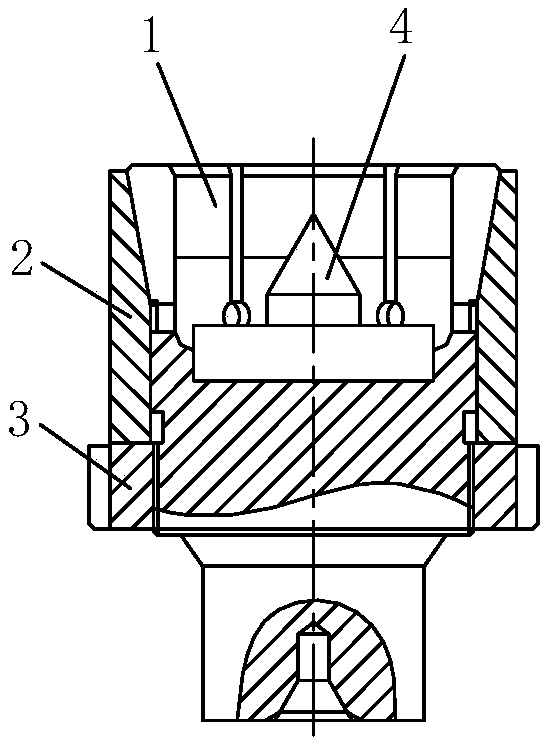
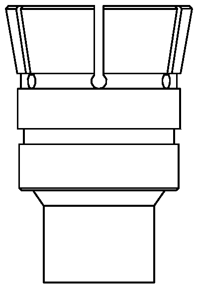
[0029] Such as figure 1 with figure 2 As shown, the present invention includes an elastic collet body 1, a sliding taper sleeve 2 and a lock nut 3. The sliding taper sleeve 2 is sleeved on the clamping portion of the elastic collet body 1 and can be moved along the clamping portion Sliding up and down, the locking nut 3 is threaded on the collet body 1 and is used to push the sliding taper sleeve 2 to slide, the locking nut 3 is located under the sliding taper sleeve 2, the elastic collet body 1 A self-centering top 4 is fixed in the clamping hole.

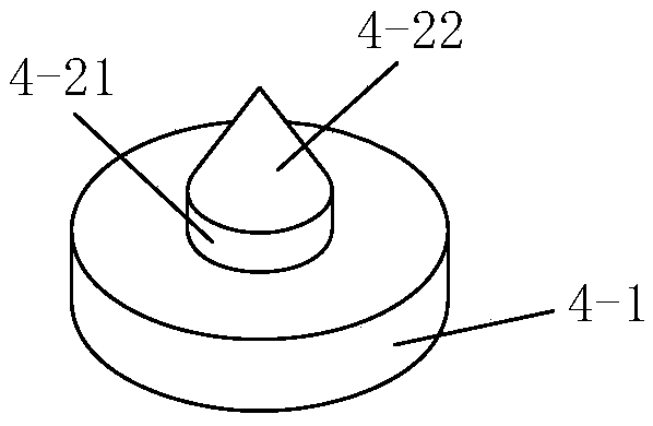
[0030] Such as image 3 As shown, the self-centering center 4 includes a center seat 4-1 and a center head 4-2, the center head 4-2 is fixed at the top center of the center seat 4-1, and the center seat 4-1 is fixed At the center of the clamping hole; the role of the center seat 4-1 is to fix the center head 4-2 on the one hand, and to stably fix the self-centering center 4 in the clamping hole on the other hand.

[0031] Suc...


PUM


Abstract

The invention discloses a self-centering spring clamping device which comprises an elastic collet body, a sliding conical sleeve and a locking nut. A clamping portion of the elastic collet body is sleeved with the sliding conical sleeve, and the sliding conical sleeve can slide up and down along the clamping portion. The locking nut is in threaded connection with the elastic collet body and used for pushing the sliding conical sleeve to slide. The locking nut is located below the sliding conical sleeve. A self-centering center is fixedly arranged inside a clamping hole of the elastic collet body. The self-centering spring clamping device is simple in structure, novel and reasonable in design and convenient to install and use, the problems that an existing shaft type gear is not convenient to machine and install and long in adjustment time and wastes time and labor during adjustment are solved, self-centering of the shaft type gear can be conveniently achieved, the clamping precision of the shaft type gear is high, and the machining precision of the shaft type gear can be ensured.

Description

technical field [0001] The invention belongs to the technical field of machine tool processing, and in particular relates to a self-centering spring clamping device. Background technique [0002] For the processing of shaft gears, the shaft diameter of the shaft gears is too large or too small and the length of the shaft, etc., will cause the shaft gears to be clamped on the machine tool for processing, and the grinding wheel cannot be punched out of the tooth groove, resulting in the gears not being able to be precisely Processing or processing clamping is difficult. Therefore, the machining of shaft gears usually requires transition sleeves to fix the shaft gears on the machine tool for processing. During specific processing, one end of the transition sleeve and an end of the shaft gear are fixed, the other end of the transition sleeve is fixed on the collet of the machine tool, and the other end of the shaft gear is tightly fastened on the tailstock top of the machine to...

Claims


Application Information

Patent Timeline
IPC IPC(8): B23F23/06
CPCB23F23/06
Inventor 姚晓涛苗青
Owner 西安贝吉姆机床股份有限公司
Learn More