Movable centre mechanism of numerical control worm grinding wheel gear grinding machine

A technology of worm grinding wheel and gear grinding machine, which is applied in the direction of gear teeth, worms, gear cutting machines, etc. It can solve the problems of affecting the machining accuracy, poor contact between the tip and the tip hole of the workpiece, etc., to improve the grinding accuracy, avoid deformation, and install and operate convenient effect

Active Publication Date: 2016-05-04
西安贝吉姆机床股份有限公司
View PDF7 Cites 2 Cited by
  • Summary
  • Abstract
  • Description
  • Claims
  • Application Information

AI Technical Summary

Problems solved by technology

The radial position of the top of the movable top mechanism is adjusted to the screw at the end of the top positioning sleeve, and the force of the screw will force the top sleeve to shift, which will cause poor contact between the top and the top hole of the workpiece, which will affect the machining accuracy.

Method used


Image

  • Movable centre mechanism of numerical control worm grinding wheel gear grinding machine
  • Movable centre mechanism of numerical control worm grinding wheel gear grinding machine
  • Movable centre mechanism of numerical control worm grinding wheel gear grinding machine

Examples


Embodiment Construction

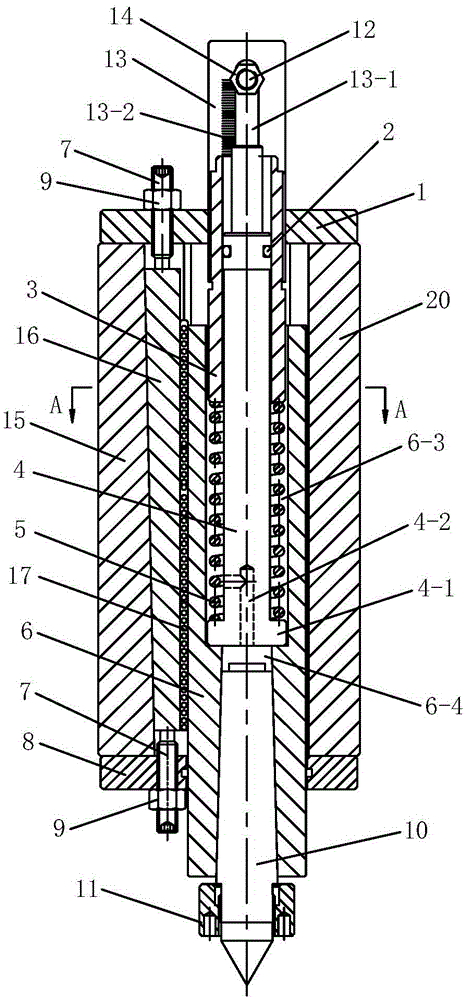
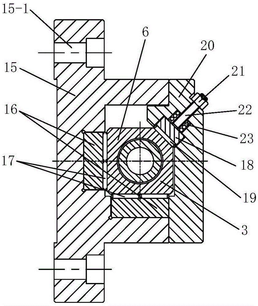
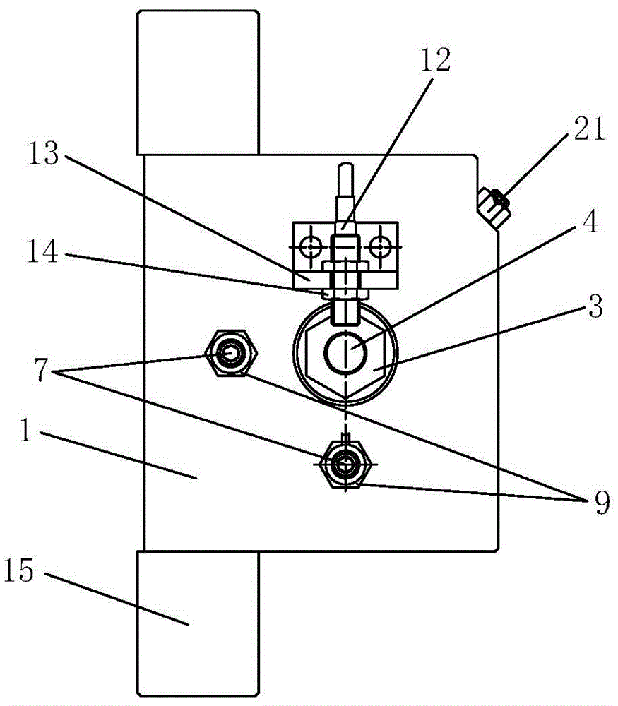
[0040] Such as figure 1 , figure 2 , image 3 , Figure 5 and Figure 6As shown, the present invention includes a top body and a top shaft 6, the top body includes a top seat 15, a cover plate 20, an upper end cover 1 and a lower end cover 8, and the cover plate 20 is arranged on one side of the top seat 15, the The upper end cover 1 is arranged on the top of the top seat 15, the lower end cover 8 is arranged on the bottom of the top seat 15, the top seat 15, the cover plate 20, the upper end cover 1 and the lower end cover 8 are fixed together and the four are fixed together. A cavity is formed between them, the upper part of the tip shaft 6 is arranged in the cavity, the lower part of the tip shaft 6 passes through the lower end cover 8 and is located outside the cavity, and the Morse tip 10 is installed on the tip shaft 6 , the upper part of the tip shaft 6 is provided with a right-angled surface 6-1, and a first plate roller chain 17 and a beveled strip 16 are arrange...


PUM


Abstract

The invention discloses a movable centre mechanism of a numerical control worm grinding wheel gear grinding machine. The movable centre mechanism of the numerical control worm grinding wheel gear grinding machine comprises a centre body and a centre shaft. The centre body comprises a centre base, a cover plate, an upper end cover and a lower end cover. The centre base, the cover plate, the upper end cover and the lower end cover are fixed together, and a cavity is formed among the centre base, the cover plate, the upper end cover and the lower end cover. The upper portion of the centre shaft is arranged in the cavity. The lower portion of the centre shaft penetrates out of the lower end cover. A Morse centre is installed on the centre shaft. A right-angle face is arranged on the upper portion of the center shaft. A first plate type rolling column chain and an inclined inlaid strip are arranged between each of the two straight faces of the right-angle face and the inner wall of the centre base. The bevels of the inclined inlaid strips are matched with the bevel of the inner wall of the centre base. The upper end cover and the lower end cover are both in a threaded connection with a first jackscrew. First locking nuts are arranged on the first jackscrews. The length of the inclined inlaid strips is smaller than the height of the cavity. The first plate type rolling column chains are shorter than the inclined inlaid strips. A tight ejecting mechanism is arranged on the cover plate. By means of the movable centre mechanism, the radial position of a centre and the pressing force of the centre on a workpiece can be precisely adjusted, adjustment is convenient, and adjusting precision is high.

Description

technical field [0001] The invention belongs to the technical field of gear grinding machines, and in particular relates to a movable top mechanism of a numerically controlled worm grinding wheel gear grinding machine. Background technique [0002] The movable top mechanism is the main clamping part of the CNC worm wheel gear grinding machine. For the processing of slender workpieces, the movable top mechanism needs to be used in conjunction with the turntable of the CNC worm wheel gear grinder to ensure the rotation center of the slender workpiece and the rotation center of the turntable. On one line, improve machining accuracy. Generally speaking, there will always be an assembly error in the top rotation of the turntable. As the length of the workpiece increases, this error will be enlarged. In order to ensure that the center of rotation of the turntable and the center of rotation of the workpiece are in a straight line as much as possible, the top of the tailstock (mova...

Claims


Application Information

Patent Timeline
Patent Type & Authority Applications(China)
IPC IPC(8): B23F23/06B23F13/00
CPCB23F13/006B23F23/06
Inventor 宋彦明李建军苗青
Owner 西安贝吉姆机床股份有限公司
Why Eureka
Try Eureka