Four-axis rotating jig

A jig and four-axis machine technology, applied in the field of machining, can solve the problems of complex process, high time consumption and low production efficiency.

Inactive Publication Date: 2016-05-04
SUZHOU JOYO METAL TECH CO LTD
View PDF7 Cites 8 Cited by
  • Summary
  • Abstract
  • Description
  • Claims
  • Application Information

AI Technical Summary

Problems solved by technology

[0004] The invention provides a four-axis rotary jig to solve the problems in the prior art

Method used


Image

  • Four-axis rotating jig
  • Four-axis rotating jig

Examples


Embodiment Construction

[0019] The present invention is described in detail below in conjunction with accompanying drawing:

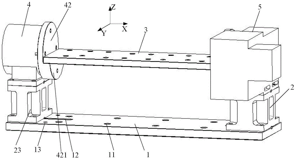
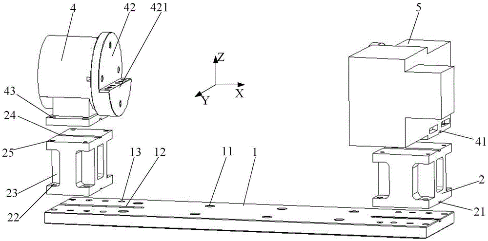
[0020] Such as figure 1 As shown, the present invention provides a four-axis rotating jig, including a base plate 1, supports 2 arranged on both sides above the base plate 1, a four-axis rotating device arranged above the support 2, and the The processing table 3 connected with the four-axis rotating device, the four-axis rotating device includes a four-axis base 4 and a tailstock 5, and the four-axis base 4 and the tailstock 5 are respectively connected with one of the supports 2, and the four-axis base 4 and the tailstock 5 are respectively connected to one of the supports 2, and the four-axis base The shaft frame 4 and the tailstock 5 are coaxially arranged, and the processing table 3 is made of aluminum plate, and several positioning holes 31 are arranged on the processing table 3 . Specifically, a number of mounting holes 11 are provided in the middle of the bottom plate...


PUM


Abstract

The invention discloses a four-axis rotating jig which comprises a bottom plate, supports arranged on the two sides of the upper portion of the bottom plate, four-axis rotating devices arranged on the upper portions of the supports and a machining table connected with the four-axis rotating devices. Each four-axis rotating device comprises a four-axis base and a tailstock, wherein the four-axis base and the tailstock are connected with the corresponding support and arranged coaxially. The machining table is made of an aluminum plate and provided with a plurality of positioning holes. The four-axis bases and the tailstocks are effectively fixed through the bottom plate and the supports, and the four-axis rotating devices do not need to be frequently positioned and fixed, so that the procedure complexity is greatly lowered; the machining table is made of the aluminum plate and provided with the positioning holes so that workpieces of different sizes can be positioned, and adaptability is high; due to the facts that the aluminum plate is light and cutting and drilling are easy, when the positioning holes in the upper side of the machining table are too many and consequently the machining table cannot be used, the machining table can continue to be used after being cut, and the machining table does not need to be frequently replaced, so that the material utilization rate is increased.

Description

technical field [0001] The invention relates to the technical field of machining, in particular to a four-axis rotary jig. Background technique [0002] Machining includes cutting, engraving, plastic deformation and other operations on the workpiece. During the processing, the workpiece is first fixed on the processing table, and then the workpiece is processed by the cutter head. During the processing, it must be ensured that the workpiece will not Movement occurs, so as not to affect the processing effect, so the positioning of the workpiece is particularly important. At present, the positioning of the workpiece usually adopts the method of side clamping or top surface pressing. First, the workpiece is placed on the processing table, and the side clamping fixture or the top surface clamping fixture are used for the four corners of the workpiece on the side of the workpiece. Position it. However, it is difficult to control the clamping force by the side clamping method. I...

Claims


Application Information

Patent Timeline
IPC IPC(8): B23Q3/06B23Q7/02
CPCB23Q3/066B23Q7/02
Inventor 王永
Owner SUZHOU JOYO METAL TECH CO LTD
Why Eureka
Try Eureka