
Plasma-spraying-based manufacturing method for high-strength insulation mirror plate

A manufacturing method and plasma technology, which are applied in coating, fusion spraying, metal material coating process, etc., can solve the problems of surface depression, mirror plate failure, immature coating preparation process, etc., and achieve smooth and wear-resistant surface. Effect

Inactive Publication Date: 2016-05-04
SUZHOU JIAMING MACHINERY MFG
View PDF6 Cites 0 Cited by
  • Summary
  • Abstract
  • Description
  • Claims
  • Application Information

AI Technical Summary

Problems solved by technology

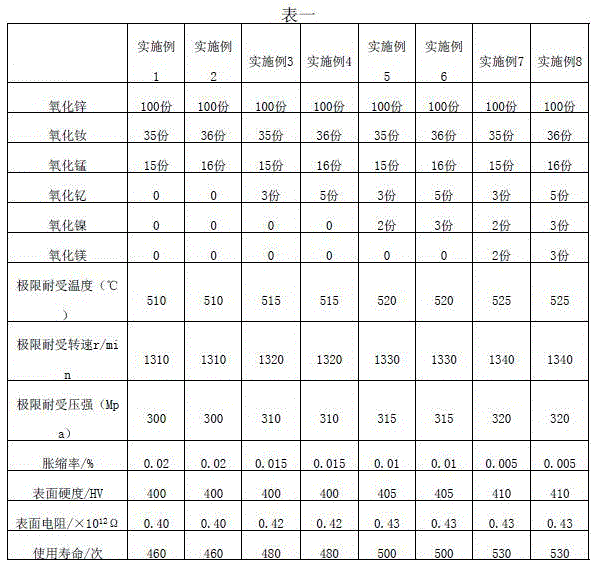
[0003] The biggest difference between the mirror plate and the ordinary insulating plate is that there is a dense coating on the surface, which has a great influence on the performance of the mirror plate. In the lamination process, the performance requirements of the mirror plate are very high. During operation, both high temperature heat (greater than 300°C) and strong pressure (greater than 50MPa) are generated, which requires the mirror plate to have excellent thermal pressure resistance, that is, the mirror plate needs to have a very high limit temperature resistance And the ultimate pressure resistance, and, more importantly, the surface coating of the mirror plate must remain very smooth and smooth after repeated hot pressing, without depressions on the surface, and no expansion and contraction. This requirement cannot be realized in the process. Generally, the mirror plate of the prior art can be used for about 100 times at room temperature, and then the surface begins to be sunken, resulting in the failure of the mirror plate, and it can only be used about 50 times at high temperature. has expired
The main reason why the existing technology cannot meet this requirement is that the preparation process of this coating is not yet mature, more specifically, the combination of the coating formula and the coating construction process is not yet perfect.

Method used


Image

  • Plasma-spraying-based manufacturing method for high-strength insulation mirror plate

Examples


Embodiment Construction

[0020] The present invention will be further described in detail below in conjunction with the embodiments, so that those skilled in the art can implement it with reference to the description.

[0021] This case proposes an embodiment of a method for manufacturing a high-strength insulating mirror plate based on plasma spraying, including the following steps:

[0022] 1) Dry the substrate to be sprayed after pickling and degreasing;

[0023] 2) corona treatment of the substrate;

[0024] 3) Spray the coating powder onto the surface of the substrate by plasma spraying method;

[0025] Wherein, the coating powder comprises the following materials by weight:

[0026] Zinc oxide 100 parts by weight;

[0027] Neodymium oxide 35~36 parts by weight;

[0028] 15-16 parts by weight of manganese oxide.

[0029] In the above embodiments, the substrate is an aluminum plate or a stainless steel plate.

[0030] In the above embodiments, the coating powder further includes 3-5 parts by...


PUM


Abstract

The invention discloses a plasma-spraying-based manufacturing method for a high-strength insulation mirror plate. The method comprises the following steps that firstly, a substrate to be sprayed is subject to acid pickling, degreasing and drying; secondly, the substrate is subject to corona treatment; and thirdly, coating powder is sprayed to the surface of the substrate through a plasma spraying method, wherein the coating powder comprises, by weight, 100 parts of zinc oxide, 35 parts to 36 parts of neodymium oxide and 15 parts to 16 parts of manganese oxide. According to the plasma spraying technology, the formula of the coating powder is designed in a brand-new manner, the formula can be well suitable for the plasma spraying technology, a compact coating is formed on the surface of the substrate, and through the coating, it can be ensured that when being subject to hot pressing at the high temperature and under the high pressure, the insulation mirror plate is used in a high-frequency manner, and does not expand and shrink, and the surface is flat, wear-resisting and free of sinking.

Description

technical field [0001] The invention relates to a method for manufacturing an insulating mirror plate, in particular to a method for manufacturing a high-strength insulating mirror plate based on plasma spraying. Background technique [0002] When manufacturing the main substrate of the circuit board (PCB), it is necessary to use a voltage machine to laminate multiple layers of different materials. The working principle of this voltage machine is to heat the processed glue through copper foil (or aluminum foil) Adhesive resin material, and press the multi-layer material by applying a certain pressure for at least half an hour, so as to make the circuit board base material, and in the process of pressing with an electric machine, due to cost considerations, a single pressing operation often needs to be done at the same time. Pressing multiple pieces of circuit board substrates, and in order to prevent multiple pieces of circuit board substrates from being affected by each oth...

Claims


Application Information

Patent Timeline
Patent Type & Authority Applications(China)
IPC IPC(8): C23C4/11C23C4/134
Inventor 沈金明
Owner SUZHOU JIAMING MACHINERY MFG
Learn More