Assessment method for optimal installation configuration of inertial measurement unit with two-frequency mechanically-dithered laser gyroscopes

A technology of inertial measurement unit and machine-shaking laser gyro, which is applied in the field of guidance and control and inertial navigation, can solve the problems of reduced reliability, reduced precision, and easy-to-interference circuits, so as to improve the accuracy and reliability of use, prolong the service life, highly operable effect

Active Publication Date: 2016-05-04
NAT UNIV OF DEFENSE TECH
View PDF6 Cites 10 Cited by
  • Summary
  • Abstract
  • Description
  • Claims
  • Application Information

AI Technical Summary

Problems solved by technology

The disadvantage of the digital jitter control system of square wave jitter is that square wave jitter has rich high-order harmonics, which can easily interfere with other circuits
[0007] However, the above-mentioned documents all start with the shaking control of a single two-frequency machine-jittered laser gyroscope, aiming at how to make the mechanical shaker frequency bias mechanism of the two-frequency machine-jittered laser gyroscope work in a normal state
In the actual construction of a two-frequency machine-jittered laser gyro strapdown inertial navigation system, the two-frequency machine-jittered laser gyroscope is always installed on the same mounting base in the inertial measurement unit, and usually three orthogonal installations or three More than two redundant installations, in this way, the high-frequency angular vibrations of the mechanical vibration bias mechanism of each two-frequency machine-jitter laser gyroscope will excite each other to generate coupling vibration, and at the same time, the high-frequency angular vibration of the mechanical vibration bias mechanism of the two-frequency machine-shake laser gyro The frequency angular vibration will also excite the installation base to generate coupling vibration. When thes

Method used


Image

  • Assessment method for optimal installation configuration of inertial measurement unit with two-frequency mechanically-dithered laser gyroscopes
  • Assessment method for optimal installation configuration of inertial measurement unit with two-frequency mechanically-dithered laser gyroscopes
  • Assessment method for optimal installation configuration of inertial measurement unit with two-frequency mechanically-dithered laser gyroscopes

Examples


Embodiment Construction

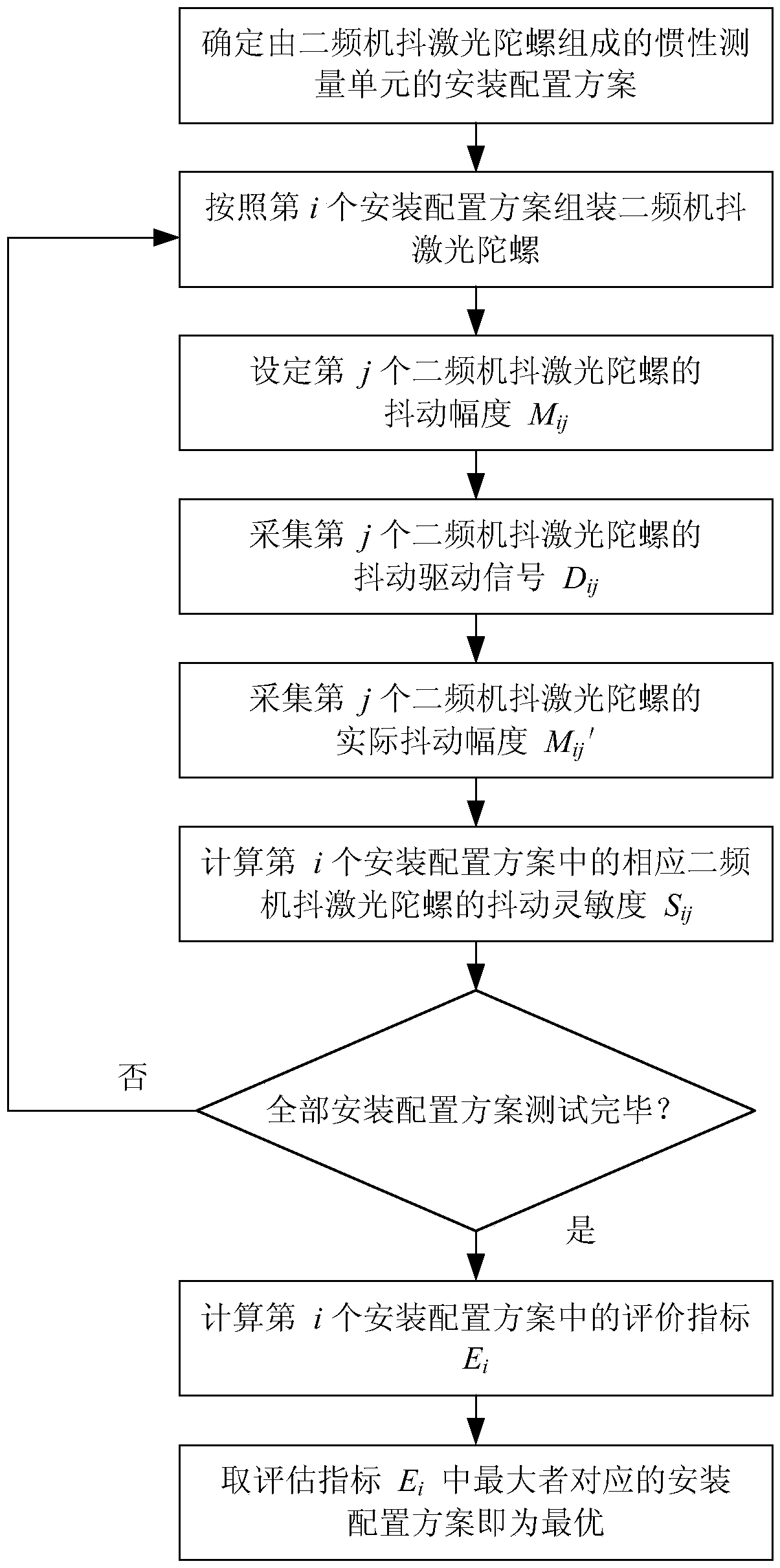
[0039] The specific implementation scheme adopted for realizing the object of the invention is:

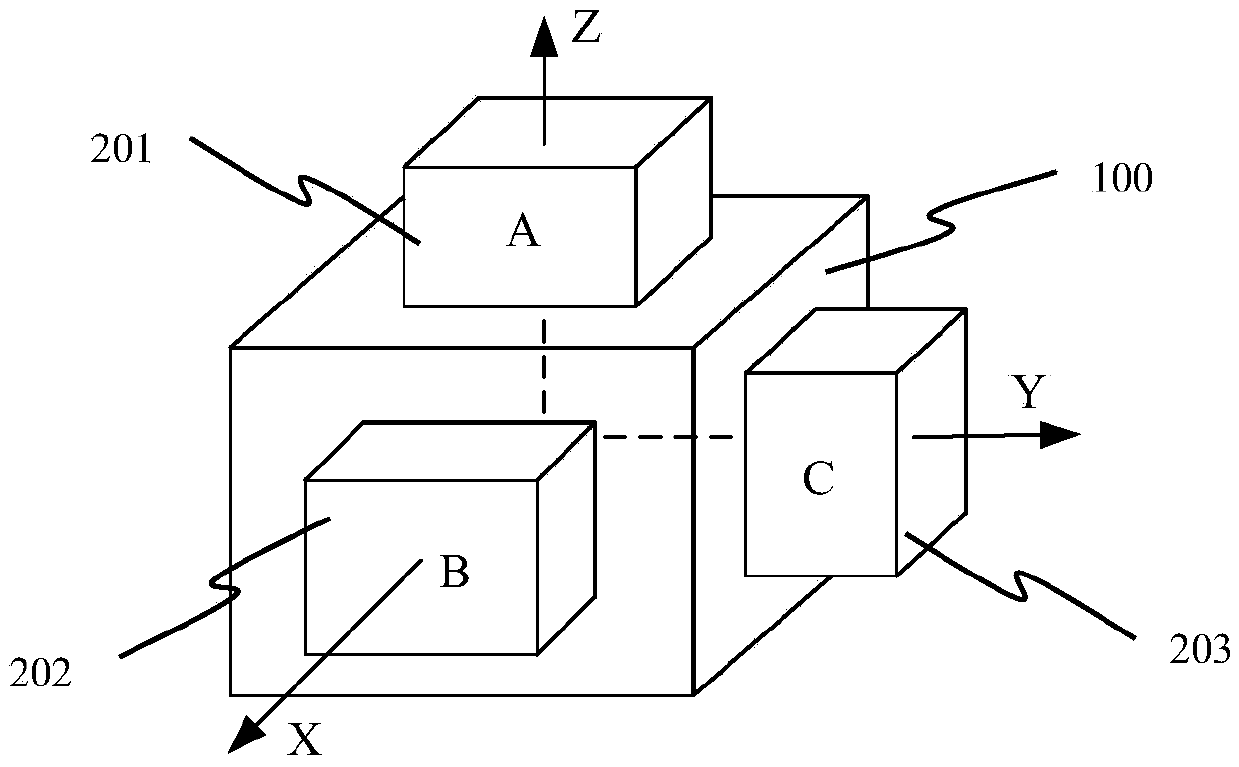
[0040] As an example, consider the design of an orthogonally mounted IMU such as figure 2 As shown, there are three orthogonal mounting surfaces on the mounting base 100 in the inertial measurement unit, and the normal directions of the mounting surfaces are respectively defined as X, Y, and Z directions. The models are defined as A, B, and C types according to the level of the natural frequency of the jitter. figure 2 It is an installation configuration scheme: Type A two-frequency machine-shaking laser gyro 201 is installed in the Z direction of the installation base 100, B-type two-frequency machine-shaking laser gyro 202 is installed in the X direction of the installation base 100, and C-type two-frequency machine The dithering laser gyro 203 is installed in the Y direction of the installation base 100 . ,

[0041] Step 1. Define three installation orientations as X, Y, a...


PUM


Abstract

The invention discloses a dithering sensitivity-based assessment method for the dithering sensitivities of two-frequency mechanically-dithered laser gyroscopes, and belongs to the field of inertial navigation, guidance and control. The method comprises the steps that 1, the target dithering amplitudes of the two-frequency mechanically-dithered laser gyroscopes are set; 2, the driving voltage of the two-frequency mechanically-dithered laser gyroscopes is collected; 3, the actual dithering amplitudes of the two-frequency mechanically-dithered laser gyroscopes are collected; 4, the dithering sensitivities of the two-frequency mechanically-dithered laser gyroscopes installed on an inertial measurement unit under the different installation configurations are calculated; 5, the dithering sensitivities of the two-frequency mechanically-dithered laser gyroscopes under the different configurations are compared, and then the optimal installation configuration scheme of the inertial measurement unit with the two-frequency mechanically-dithered laser gyroscopes is obtained. When the method is used for designing the inertial measurement unit composed of the two-frequency mechanically-dithered laser gyroscopes, the configuration scheme with the most suitable dithering frequency and installation positions is selected, it is guaranteed that the inertial measurement unit can work in the best state, the using precision of the two-frequency mechanically-dithered laser gyroscopes is improved, and the service life of the two-frequency mechanically-dithered laser gyroscopes is prolonged.

Description

technical field [0001] The invention relates to an evaluation method for optimal installation and configuration of a two-frequency machine-jittered laser gyro inertial measurement unit based on shaking sensitivity, and belongs to the field of inertial navigation, guidance and control. Background technique [0002] The laser gyroscope is a device for measuring angular rate and angle based on the Sagnac effect and composed of a ring laser resonator. Among the error sources of laser gyroscopes, the region-locking effect is one of the main error sources that limit the practical application of laser gyroscopes. The lock-in effect refers to the phenomenon that the output of the laser gyroscope is zero under the condition of low input angular rate. There are many ways to overcome the lock-in effect, such as rate bias, mechanical jitter bias, Zeeman bias, magnetic mirror bias and Faraday bias, etc. The basic idea is to make the working state of the laser gyroscope quickly cross the...

Claims


Application Information

Patent Timeline
IPC IPC(8): G01C21/16G01C19/66
CPCG01C19/66G01C21/16
Inventor 李耿谢元平张鹏飞魏国于旭东龙兴武
Owner NAT UNIV OF DEFENSE TECH
Why Eureka
Try Eureka