
Embedded bridge health monitoring system

A bridge health monitoring and embedded technology, applied in the transmission system, signal transmission system, digital transmission system, etc., can solve the problems of burning hardware equipment, no priority, cost increase, etc., and achieve the effect of ensuring continuity

Inactive Publication Date: 2016-05-04
LIAONING PROVINCIAL TRANSPORTATION PLANNING & DESIGN INST
View PDF8 Cites 6 Cited by
  • Summary
  • Abstract
  • Description
  • Claims
  • Application Information

AI Technical Summary

Problems solved by technology

[0002] At present, the communication architecture of the existing bridge health monitoring system is mainly based on parallel 485 communication and 485 bus, but the parallel 485 architecture adopts a multi-channel parallel structure on the hardware, which doubles the cost. In addition, the 485 bus master control program needs To achieve multi-channel coordination work, there is no strict priority among channels. Once a concurrent phenomenon occurs, it is easy to cause data loss; at the same time, the 485 bus has low voltage resistance. When there are too many sensor nodes connected in parallel, it is easy to appear The phenomenon that the bus current caused by concurrent faults is too large and the hardware equipment is burned, the publication number is 101916507A, and the name of the invention is "Bridge Health Monitoring System". It provides a bridge health monitoring system that can establish a large-scale monitoring network, but the communication structure Not complete, for parallel 485 communication and 485 bus, because there is no complete communication control mechanism like CAN bus, when a single sensor fails and uploads data continuously, it will cause system paralysis

Method used


Image

  • Embedded bridge health monitoring system
  • Embedded bridge health monitoring system
  • Embedded bridge health monitoring system

Examples


Embodiment Construction

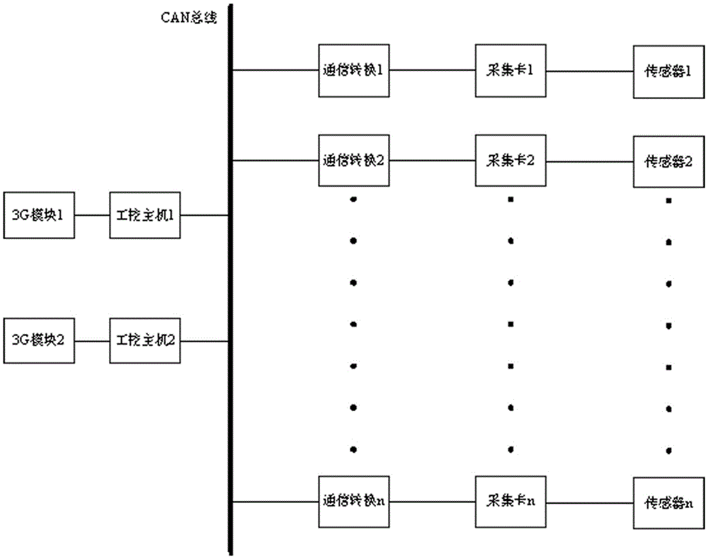
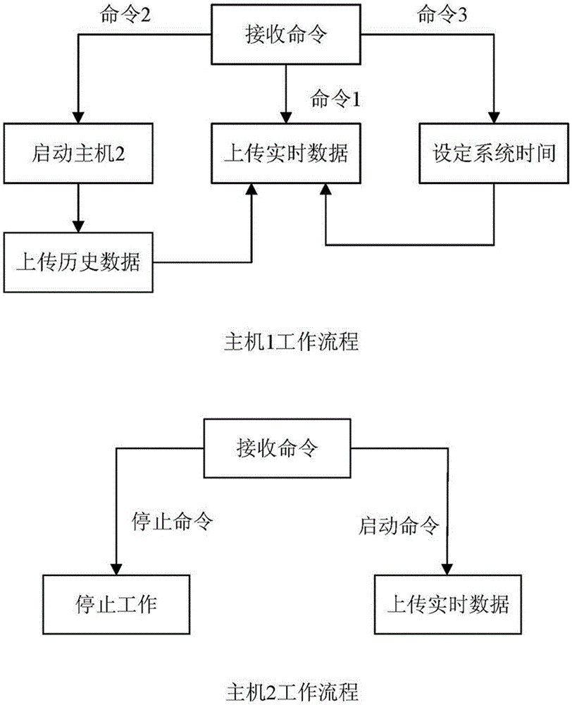
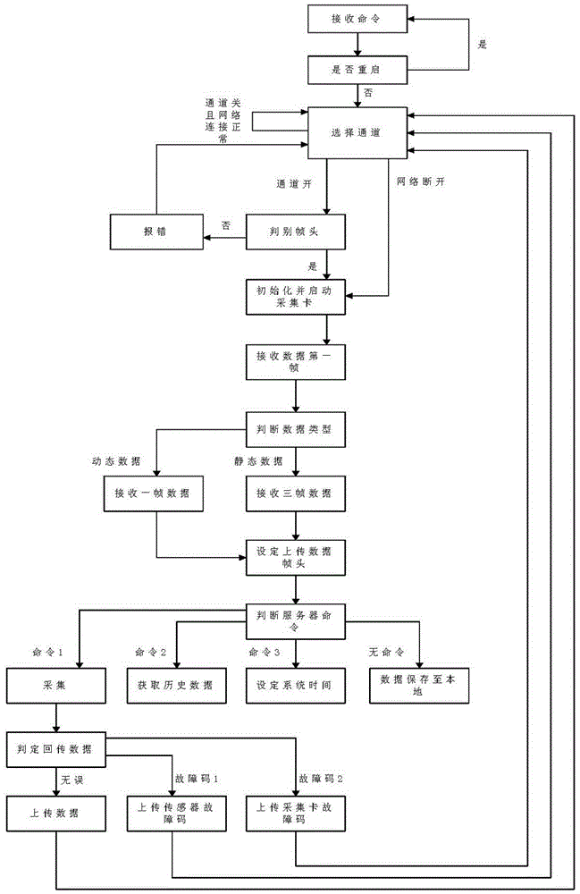
[0014] like figure 1 As shown, the present invention relates to an embedded bridge health monitoring system, including a 3G wireless module, an industrial control host, an acquisition card and a sensor, wherein the industrial control host is used to execute the commands issued by the host computer, and control the acquisition card to complete the data according to the host computer commands. Acquire and receive the data from the acquisition card, organize and package the data, and send the data to the host computer server, the 3G wireless module is used to send and receive data through the public network, and the acquisition card is used to convert the analog signal in the sensor into a digital signal , the sensor is used to collect the measured information, a communication conversion module is connected between the industrial control host and the acquisition card, the 3G wireless module is connected to the industrial control host, the industrial control host is connected to th...


PUM


Abstract

The invention relates to an embedded bridge health monitoring system which is used for assisting in bridge maintenance work and monitoring old-bridge health conditions in real time. The embedded bridge health monitoring system comprises 3G wireless modules, industrial control mainframes, collection cards and sensors; a communication conversion module is connected between each industrial control mainframe and the corresponding collection card, each 3G wireless module is connected with the corresponding industrial control mainframe, each industrial control mainframe is connected with the corresponding communication conversion module, each communication conversion module is connected with the corresponding collection card, and each collection card is connected with the output end of the corresponding sensor. A CAN bus communication mode is adopted between the industrial control mainframes and the communication conversion modules, a 485 communication mode is adopted between the communication conversion modules and the collection cards, and a two-mainframe construction mode is adopted by the monitoring system. The embedded bridge health monitoring system has the prominent advantages that by means of the system, continuity, orderliness and accuracy of monitoring system data can be guaranteed, stable operation of the system can be better guaranteed, and therefore serious consequences caused by bridge collapse events are avoided.

Description

technical field [0001] The invention relates to the technical field of bridge engineering signal transmission, in particular to an embedded bridge health monitoring system. Background technique [0002] At present, the communication architecture of the existing bridge health monitoring system is mainly based on parallel 485 communication and 485 bus, but the parallel 485 architecture adopts a multi-channel parallel structure on the hardware, which doubles the cost. In addition, the 485 bus master control program needs To achieve multi-channel coordination work, there is no strict priority among channels. Once a concurrent phenomenon occurs, it is easy to cause data loss; at the same time, the 485 bus has low voltage resistance. When there are too many sensor nodes connected in parallel, it is easy to appear The phenomenon that the bus current caused by concurrent faults is too large and the hardware equipment is burned, the publication number is 101916507A, and the name of t...

Claims


Application Information

Patent Timeline
IPC IPC(8): G08C17/02G08C19/00H04L12/40
CPCG08C17/02G08C19/00H04L12/40176H04L12/40202
Inventor 崔凯华张冠华于传君韩基刚侯娜梁玉敏孙福民王秋实王佳伟
Owner LIAONING PROVINCIAL TRANSPORTATION PLANNING & DESIGN INST
Learn More