Molten core catcher with interior cooling capacity

A core melt and internal cooling technology, applied in cooling devices, reactors, nuclear power generation, etc., can solve the problems of not considering the internal cooling method of the melt, long migration path of the melt, and many links, so as to reduce the instantaneous steam Production volume, reliable cooling method, effect of reducing metal content

Active Publication Date: 2016-05-04
CHINA NUCLEAR POWER ENG CO LTD
View PDF18 Cites 13 Cited by
  • Summary
  • Abstract
  • Description
  • Claims
  • Application Information

AI Technical Summary

Problems solved by technology

[0008] The core catcher applied to EPR requires a larger expansion chamber, and the melt migration path is longer and has many links; the core catcher applied to WWER1000 needs at least 10 months to recover after the melt is retained. The melt is finally cooled; the cor

Method used


Image

  • Molten core catcher with interior cooling capacity
  • Molten core catcher with interior cooling capacity
  • Molten core catcher with interior cooling capacity

Examples


Embodiment Construction

[0024] The present invention will be described in detail below in conjunction with the accompanying drawings and embodiments.

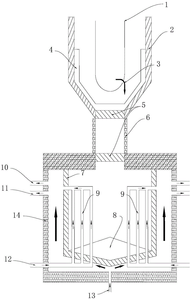
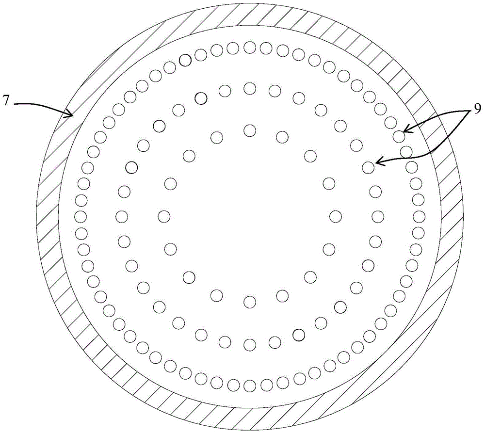
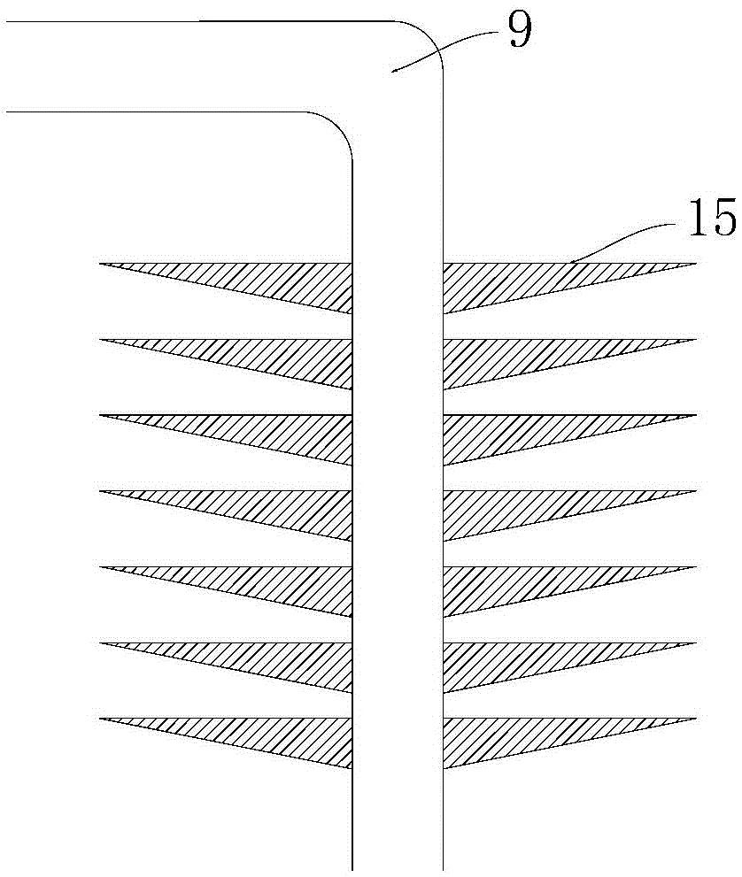
[0025] Such as figure 1 As shown, the present invention provides a core melt catcher with melt internal cooling capability, comprising a melt retention vessel 7, which is located in a reactor pit 2 via a vertical transfer channel 6 In the vertical shaft 14, the upper part of the vertical transportation channel 6 has a fusible layer 5, and the lower part of the reactor pit 2 has a layer of sacrificial concrete 4. In this embodiment, the bottom of the smelt retention vessel 7 is in an inverted conical shape, and the inclination angle of the conical surface is 8-20°. The sacrificial material 8 and the inner tube bundle 9 are arranged inside, and the water inlet 12 of the inner tube bundle is located at the shaft 14 and the smelt retention vessel. 7 bottom, the outlet is located at the upper part of the smelt retention vessel 7. The bottom of the shaft ...


PUM


Abstract

The invention relates to designing technology of reactor safety systems, specifically to a molten core catcher with interior cooling capacity. The molten core catcher comprises a melt retaining container arranged in a vertical shaft vertically connected with the bottom of a reactor pit, a plurality of interior tube bundles arranged in the melt retaining container and used for injecting a coolant and a sacrificial material arranged in the outer tube walls of the interior tube bundles and in the melt retaining container. Under a working condition of a serious accident, the molten core catcher provided by the invention can realize maximization of removal of the heat of melts by exchanging heat through the tube bundles distributed in the molten core catcher and injecting cooling water formed by later burning-up of the interior tube bundles for cooling, so long-term security of a nuclear power plant after the serious accident is guaranteed.

Description

technical field [0001] The invention relates to the reactor safety system design technology, in particular to a core melt catcher with internal cooling capacity. Background technique [0002] The ultimate goal of nuclear power plant safety design is to prevent large-scale leakage of radioactivity, and three barriers are set up for this purpose: fuel cladding, primary circuit pressure boundary and containment vessel. In the event of an accident, if the core fuel elements cannot be cooled quickly and effectively to take away the decay heat, the residual heat of the core will cause the coolant to evaporate and be exhausted, the core will be exposed, the fuel elements will continue to heat up, and finally the fuel cladding will melt (The accident developed into a serious accident at this time), and then the relevant reactor internals were melted and fell into the lower head of the reactor pressure vessel (RPV) to form a molten pool of core melt. If effective measures cannot be ...

Claims


Application Information

Patent Timeline
IPC IPC(8): G21C9/016G21C15/18
CPCG21C9/016G21C15/18Y02E30/30
Inventor 李炜韩旭郭强朱晨林斌张丽于明锐刘卓马卫民元一单
Owner CHINA NUCLEAR POWER ENG CO LTD
Why Eureka
Try Eureka