Control circuit and control method for delayed amplification component

A technology of delay amplifying components and timing control circuits, applied in amplifiers, amplifiers with semiconductor devices/discharge tubes, electrical components, etc., can solve the problems of time delay, large static power consumption, static power consumption, etc., to reduce The effect of static power consumption, development cost saving, and high reliability

Active Publication Date: 2016-05-04
CHINA ELECTRONIC TECH GRP CORP NO 38 RES INST
View PDF6 Cites 5 Cited by
  • Summary
  • Abstract
  • Description
  • Claims
  • Application Information

AI Technical Summary

Problems solved by technology

This method will cause the switching of the two switches to be asynchronous, have a time delay, and increase the complexity of the circuit
Moreover, there are only two states in the circuit, the reference state and the delay state.
Because there are only two states, there must be one state that is in the working state when the component is not working, resulting in unnecessary static power consumption
[0007] In short, there is a single control sequence in the current delay amplifier component control circuit, which makes the circuit unique in use. To replace a control sequence in other devices, it is necessary to redevelop a control circuit. Not very common
There is no buffer between sending and receiving conversion, and the static power consumption is large. These unfavorable factors are particularly prominent in the application of airborne and spaceborne equipment

Method used


Image

  • Control circuit and control method for delayed amplification component
  • Control circuit and control method for delayed amplification component

Examples


Embodiment 1

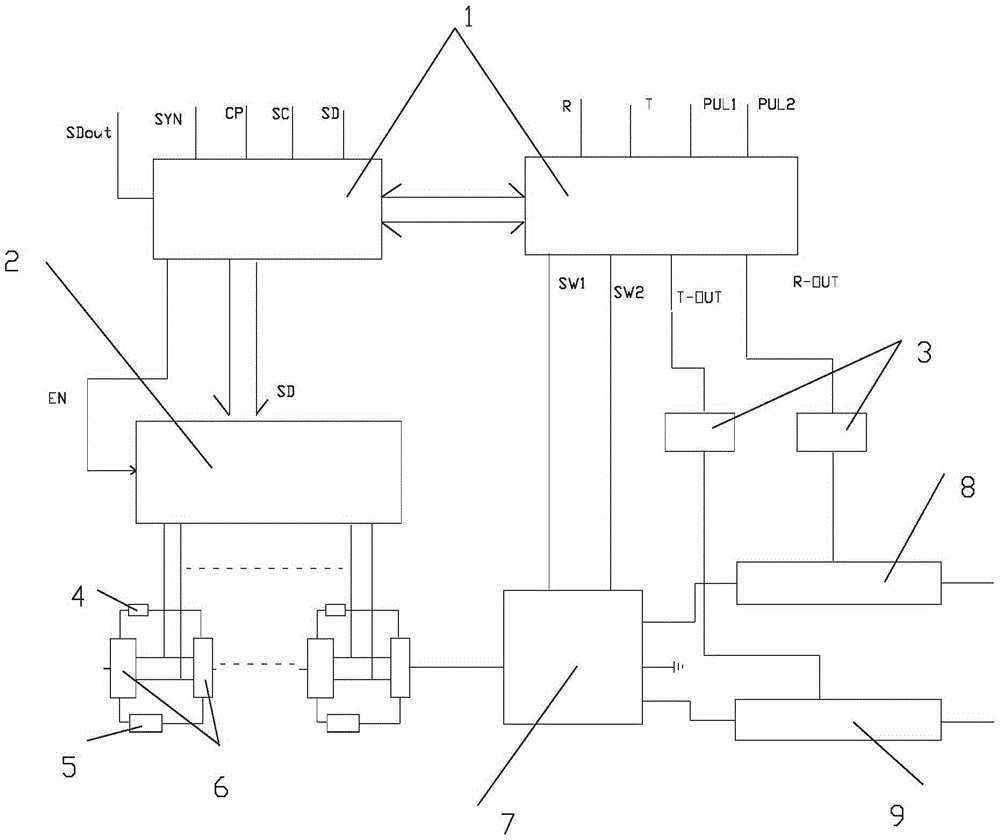
[0039] see figure 1 , a preferred embodiment is the control circuit of the C-band delay amplification component, and its component needs to realize 5-bit digital delay. The working sequence is: when the transmitting T timing and the receiving R timing are at high level at the same time, the component works in the transmitting state, and the control circuit needs to turn off the power supply of the receiving branch; when the transmitting T timing and the receiving R timing are at the same time low, To make the component work in the receiving state, the control circuit needs to turn off the power supply of the transmitting branch; when other timing combinations are used to make the component work in the load state, the control circuit needs to turn off the power supply of the entire radio frequency link at the same time.

[0040] The delay amplifier component control circuit mainly includes a timing control circuit 1 , a switch drive control circuit 2 , and a power modulation ci...

Embodiment 2

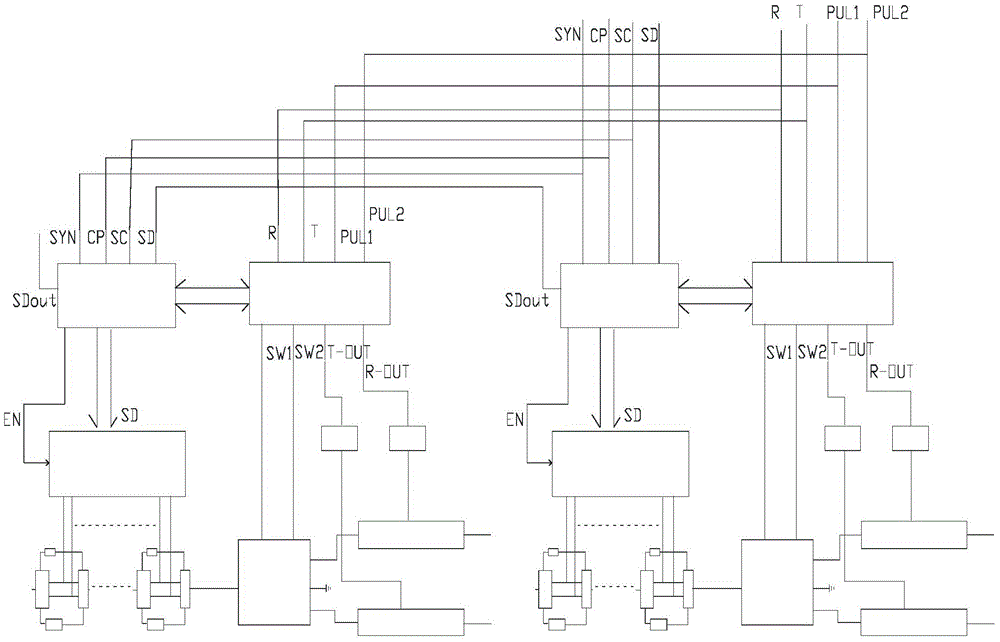
[0048] see figure 2 , another preferred embodiment of the present invention is a dual-channel delay amplifier component control circuit. The control circuit is composed of two timing control circuits directly cascaded inside, and the data overflow port of the first timing control circuit is directly connected to the data input port of the second timing control circuit. This circuit shares a timing and data port. In the case of multi-channel connection, it can greatly save the number of external interfaces and transmission cables, and reduce the size of the device.


PUM


Abstract

The invention discloses a control circuit for a delayed amplification component. The control circuit comprises a time sequence control circuit, a switch drive control circuit and a power supply modulation circuit; the time sequence control circuit receives data and a time sequence from a previous-level wave control extension, analyzes and judges the data and the time sequence, and then distributes to a next-level circuit according to an appointed time sequence relationship; the switch drive control circuit receives the data distributed by the time sequence control circuit, and controls and communicates the corresponding delay amount in the delayed amplification component according to the data combination relationship; and the power supply modulation circuit receives the data distributed by the time sequence control circuit, and judges whether power supply power is distributed to a transceiving amplification module in the delayed amplification component or not according to the appointed data relationship. The invention further provides a control method for the delayed amplification component. The control circuit and control method for the delayed amplification component disclosed by the invention have the advantages that: the problems of being low in expandability, single in control time sequence combination, non-flexible in various delay state control and high in static power consumption in the existing control circuit can be solved; free combination of the control time sequence is realized; and the control circuit disclosed by the invention has the advantages of being complementary in control of various delay state single-circuits, low in static power consumption and the like.

Description

technical field [0001] The invention relates to a control circuit, in particular to a control circuit and a control method of a delay amplifier component. Background technique [0002] With the higher and higher requirements for target recognition, phased array radar systems are developing in the direction of broadband, wide-angle scanning, and large-aperture arrays. In the phased array antenna system based on phase-shifted beam steering, within the working bandwidth, firstly, with the increase of the center frequency of the signal frequency offset and the increase of the scanning angle, the deviation of the antenna beam pointing will increase linearly; secondly, When the aperture array of the phased array antenna increases, its aperture transit time will also increase, resulting in the loss of signal synthesis of each unit. In order to overcome the limitation of the instantaneous operating bandwidth and the loss of gain brought about by the phase shifting beam steering, th...

Claims


Application Information

Patent Timeline
Patent Type & Authority Applications(China)
IPC IPC(8): H03F3/217
CPCH03F3/217
Inventor 戈海清刘永锋谢成发何建平季飞
Owner CHINA ELECTRONIC TECH GRP CORP NO 38 RES INST
Why Eureka
Try Eureka