Automatic receiving device of numerical control lathe

A technology for CNC lathes and splicing devices, which is applied in the direction of automatic in/out of workpieces, metal processing mechanical parts, metal processing, etc. The effect of reducing manpower, stable and safe operation, and small position deviation

Active Publication Date: 2016-05-11
SHENZHEN KING TEAM PRECISION TECH
View PDF9 Cites 4 Cited by
  • Summary
  • Abstract
  • Description
  • Claims
  • Application Information

AI Technical Summary

Problems solved by technology

When performing cutting operations, the operator first securely installs the blank to be processed on the chuck, and then installs the corresponding tool. After setting the processing parameters, close the safety door of the cutting area of ​​the CNC lathe, and the CNC lathe is ready. The cutting operation can be carried out according to the requirements. After the processing operation is completed, the chuck automatically releases the workpiece, and the workpiece falls freely to the material receiving device under the chuck. The material receiving device is exposed in the cutting area, and the cutting fluid and chips during processing are accompanied by the workpiece. Falling on the material receiving device, resulting in the mixing of chips and workpieces, which affects the life of the conveyor belt of the material receiving device. The conveyor belt transfers the workpiece and chips to the material box where the workpiece is placed. There are chips mixed in the material box, which must be cleaned manually, which affects production. efficiency
Especially when processing workpieces with high appearance requirements, it is necessary to increase a large amount of manual operation costs for manual blanking

Method used


Image

  • Automatic receiving device of numerical control lathe
  • Automatic receiving device of numerical control lathe
  • Automatic receiving device of numerical control lathe

Examples


Embodiment Construction

[0019] In order to illustrate the technical solution of the present invention more clearly, the technical solution of the present invention will be further described in detail below in conjunction with the accompanying drawings and embodiments. Obviously, the following descriptions are only some embodiments of the present invention. In other words, other embodiments can also be obtained according to these embodiments without paying creative efforts.

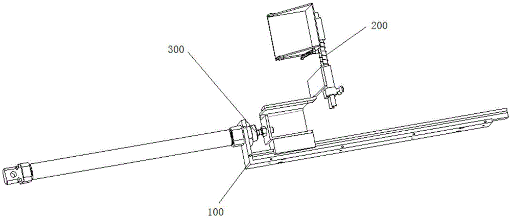
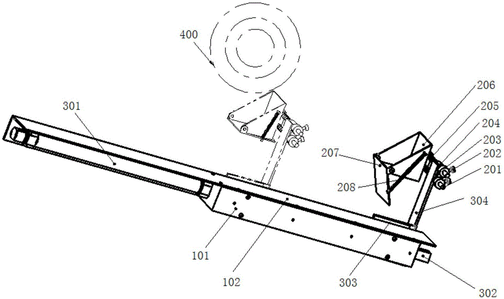
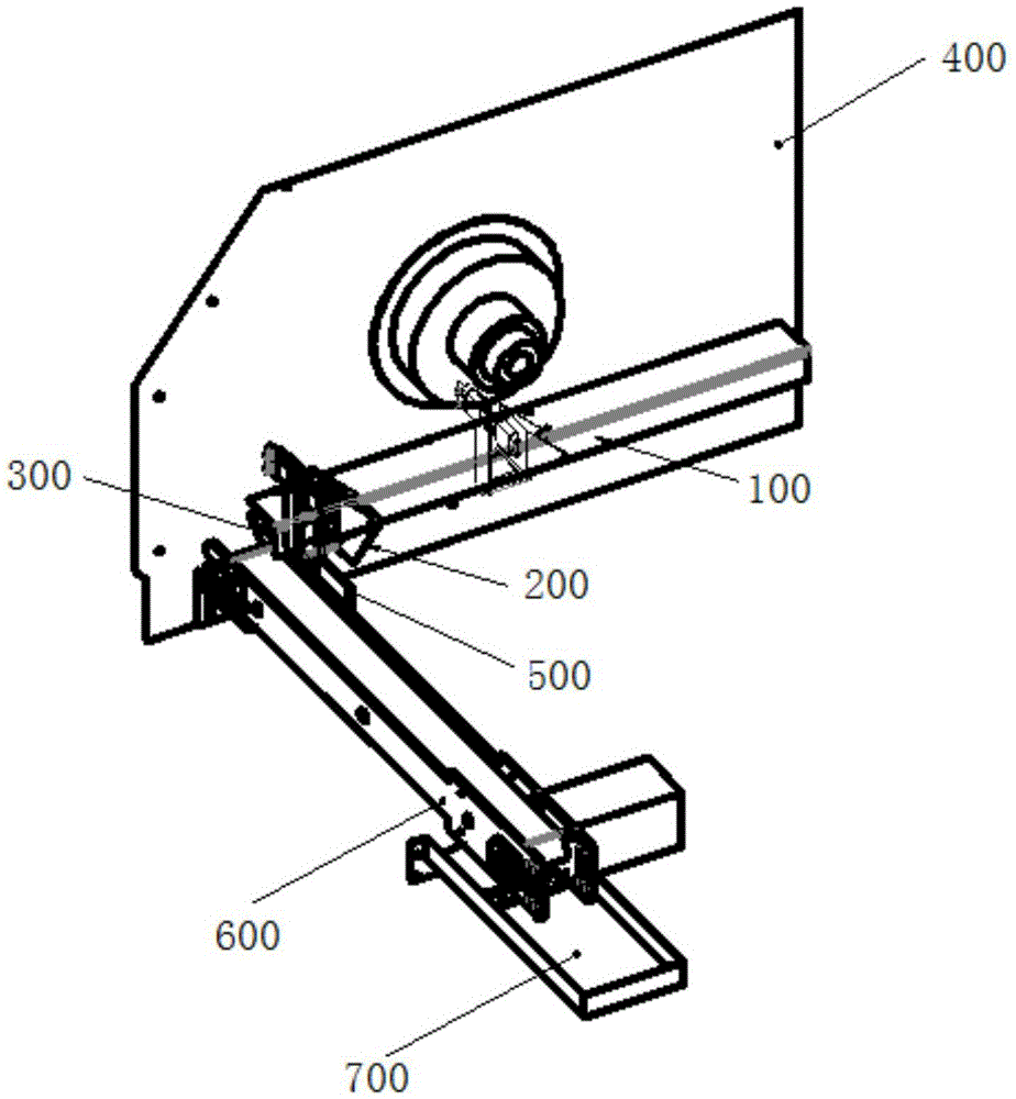
[0020] refer to Figure 1 to Figure 3 , an automatic material receiving device for a CNC lathe 400, comprising a connecting part 100 for connecting the CNC lathe 400, a material receiving part 200 for accepting workpieces, a moving part 300 for driving the material receiving part 200 to move, and a connecting part 300 connected with the CNC lathe 400 The controller connected to the control system; the controller is used to control the connection part 100, the material receiving part 200, and the moving part 300 to coordinate and ...


PUM


Abstract

The invention discloses an automatic receiving device of a numerical control lathe. The device comprises a connecting part, a receiving part, a moving part and a controller; the connecting part includes a machine tool connecting plate; the machine tool connecting plate is fixedly mounted in a preset position of the numerical control lathe through a fastening piece; the receiving part includes a buffer base, and a receiver arranged on the buffer base and with the bottom capable of being automatically opened and closed; the moving part includes a linear slide rail and a driving piece; a fixed rail of the linear slide rail is fixedly mounted on the machine tool connecting plate; a slide block of the linear slide rail is driven by the driving piece to slide along the fixed rail, and is provided with a slide bracket; and the slide bracket is connected with the buffer base of the receiving part. The automatic receiving device overcomes the defect that a traditional automatic receiving device is only suitable for a fixed cutter tower type numerical control lathe and not suitable for a slide plate type cutter arrangement lathe, and is additionally provided with the receiver to replace a traditional receiving tipping bucket to finish seamless butt joint of transporting products to a conveying belt.

Description

technical field [0001] The invention relates to an auxiliary tooling of a numerically controlled lathe, in particular to a material receiving device capable of automatically receiving a processed workpiece. Background technique [0002] The numerical control lathe of prior art, automation degree is quite high. When performing cutting operations, the operator first securely installs the blank to be processed on the chuck, and then installs the corresponding tool. After setting the processing parameters, close the safety door of the cutting area of ​​the CNC lathe, and the CNC lathe is ready. The cutting operation can be carried out according to the requirements. After the processing operation is completed, the chuck automatically releases the workpiece, and the workpiece falls freely to the material receiving device under the chuck. The material receiving device is exposed in the cutting area, and the cutting fluid and chips during processing are accompanied by the workpiece....

Claims


Application Information

Patent Timeline
Patent Type & Authority Applications(China)
IPC IPC(8): B23B15/00
CPCB23Q7/003B23Q2707/003
Inventor 吴春谅胡刚
Owner SHENZHEN KING TEAM PRECISION TECH
Why Eureka
Try Eureka