Eureka AIR delivers breakthrough ideas for toughest innovation challenges, trusted by R&D personnel around the world.

Smelting device

A smelting equipment and smelting furnace technology, applied in the field of metallurgical manufacturing, can solve the problems of long smelting cooling time and low smelting efficiency

Inactive Publication Date: 2016-05-11
宁波创润新材料有限公司
View PDF6 Cites 5 Cited by
  • Summary
  • Abstract
  • Description
  • Claims
  • Application Information

AI Technical Summary

Problems solved by technology

[0005] The problem solved by the present invention is to provide a smelting equipment to solve the problems of too long cooling time and low smelting efficiency of EB smelting

Method used


Image

  • Smelting device
  • Smelting device

Examples


Embodiment Construction

[0028] As mentioned in the background art, in the existing EB smelting, after the ingot is formed, the cooling process of the furnace body is too long, and the smelting efficiency is low.

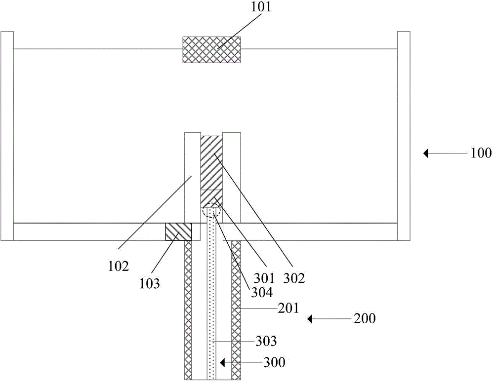
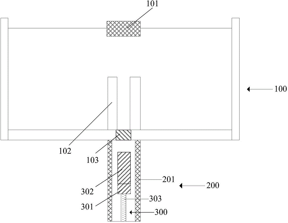
[0029] The smelting furnace body of the present invention is connected with the cooling chamber, and the smelting furnace body is provided with a crucible and an ingot pulling device. When smelting is carried out in the smelting furnace body, the crucible is used to hold the molten metal and shape the molten metal to form a casting. Ingot, the first end of the ingot pulling device is used to support the molten metal or ingot. After the molten metal is completely solidified to form an ingot, the end for supporting the molten metal or ingot can shrink from the melting furnace body to the inside of the cooling chamber, so that the ingot supported on the ingot pulling device The ingot enters the inside of the cooling chamber, and the ingot is cooled separately in the cooling chamber, so that th...


PUM


Abstract

The invention provides a smelting device. The smelting device comprises a smelting furnace, a cooling chamber and an ingot drawing device, wherein a crucible is arranged in the smelting furnace to be used for forming molten metal into an ingot, the cooling chamber is connected with the smelting furnace to be used for cooling the ingot, the ingot drawing device is provided with a first end, the first end is used for supporting the molten metal or the ingot and can be moved into the cooling chamber from the smelting furnace to enable the ingot supported by the ingot drawing device to enter the cooling chamber, and a valve is arranged between the smelting furnace and the cooling chamber. During smelting, the valve is switched off to enable the cooling chamber to be isolated from the smelting furnace, the temperature of the cooling chamber is far lower than that of the smelting furnace, and when the ingot enters the cooling chamber along with the ingot drawing device, the ingot cooling speed is higher. The smelting furnace can be cleaned while the ingot enters the cooling chamber, so that smelting time is effectively shortened.

Description

technical field [0001] The invention relates to the field of metallurgical manufacturing, in particular to a smelting equipment. Background technique [0002] EB melting, also known as electron beam melting (Electron beam melting), is a vacuum melting method that converts the kinetic energy of high-speed electron beam flow into high heat energy as a heat source for metal melting under high vacuum. [0003] Usually EB smelting is carried out in an EB smelting furnace, which is equipped with an electron gun, a feeding device, a crucible and an ingot pulling device. The method of EB smelting includes: putting the metal raw material into the feeding device, the metal raw material is melted under the bombardment of the electron beam emitted by the electron gun, and the molten metal raw material flows into the crucible, and the crucible can shape the molten metal raw material. Among them, the ingot pulling device can continuously move the metal raw material in the crucible, so th...

Claims


Application Information

Patent Timeline
Patent Type & Authority Applications(China)
IPC IPC(8): C22B9/22C22B9/04
Inventor 吴景晖姚力军邓睿
Owner 宁波创润新材料有限公司
Why Eureka
Eureka Blog
Learn More