Eureka AIR delivers breakthrough ideas for toughest innovation challenges, trusted by R&D personnel around the world.

A method for building a metallurgical furnace and its 3D printing robot

A 3D printing, metallurgical furnace technology, applied in the field of aluminum electrolysis, to avoid waste, stable performance, and protect the physical and mental health of personnel

Active Publication Date: 2018-02-23
GUIYANG AL-MG DESIGN & RES INST
View PDF5 Cites 1 Cited by
  • Summary
  • Abstract
  • Description
  • Claims
  • Application Information

AI Technical Summary

Problems solved by technology

[0003] The purpose of the present invention is to provide a method for building a metallurgical furnace and the 3D printing robot used to solve the shortcomings of the traditional method for building a metallurgical furnace

Method used


Image

  • A method for building a metallurgical furnace and its 3D printing robot
  • A method for building a metallurgical furnace and its 3D printing robot

Examples


Embodiment 1

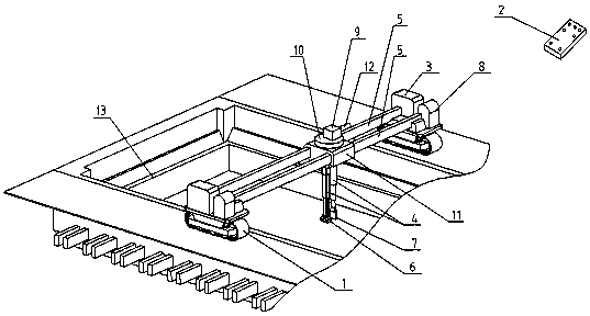
[0020] Such as figure 1 Shown, when the present invention is used for metallurgical kiln 13, implement like this:

[0021] Before building the furnace, the trolley 1 walks on the rails set on both sides of the metallurgical furnace 13, and the control system 8 drives the 3D scanner in the actuator 3 to scan the furnace in three dimensions, analyze and process the scanned data, and carry out reverse construction. Then the actuator 3 compares the modeling results with the design of the furnace, determines the area where furnace materials are added, and makes a printing plan.

[0022] When building a furnace, the positioning sensor 5 installed on the multi-dimensional motion robot arm 4 moves along with the robot arm along three dimensions in the furnace for initial positioning, and then the robot arm automatically selects a furnace building tool from the tool holder according to the printing plan 6 If the furnace hammer head is to be built, move it to the position to be built; ...

Embodiment 2

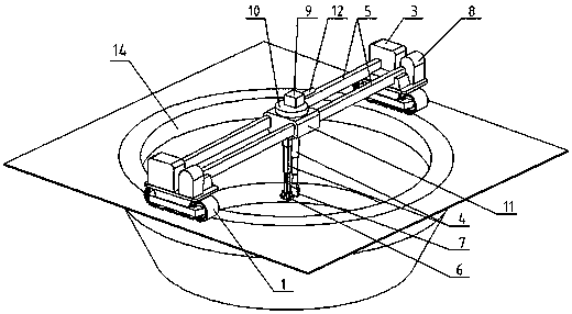
[0026] Such as figure 2 Shown, when the present invention is used for yellow phosphorus stove 14, implement like this:

[0027] Before the furnace is built, the walking trolley 1 walks on the track set in the circular direction of the yellow phosphorus furnace 14, and the control system 8 drives the 3D scanner in the actuator 3 to scan the furnace in three dimensions, analyze and process the scanned data, and carry out reverse construction. Then the actuator 3 compares the modeling results with the design of the furnace, determines the area where furnace materials are added, and makes a printing plan.

[0028] When building a furnace, the positioning sensor 5 installed on the multi-dimensional motion robot arm 4 moves along with the robot arm along three dimensions in the furnace for initial positioning, and then the robot arm automatically selects a furnace building tool from the tool holder according to the printing plan 6 If the furnace hammer head is to be built, move it...


PUM


Abstract

The invention discloses a building method of a metallurgical furnace and a 3D printing robot adopted forbuildingthe metallurgical furnace. Furnace building materials are tamped and printed in a hearth layer by layer by a 3D printing robot according to design requirements and reverse modelling results of a 3D scanner, so that a novel building furnace or the restoration of the hearth is realized. A control system of the 3D printing robot drives the 3D scanner and an execution mechanism to move for performing three-dimensional scanning on the hearth, analyzing and processing scanning data and reversely modelling; then modelling results are compared with hearth design to determine an adding area of a furnace building material, and formulate a printing plan; and in addition, multi-dimension motion robot arms drive a material distributing mechanism and a furnace building tool for building the furnace. According to the 3D printing robot adopted for building the metallurgical furnace, disclosed by the invention, material increase manufacturing can be realized according to the shape of the hearth and design requirements; an existing useable cathode is effectively utilized, the workload of planning the furnace and rebuilding the furnace is reduced, wastes are avoided and the consumption of materials such as the cathode is reduced; and the furnace building efficiency is improved, furnace building workers are reduced, labor efficiency is improved, and physical and psychological health of the workers is protected.

Description

technical field [0001] The invention relates to the technical field of aluminum electrolysis, in particular to a method for building a metallurgical furnace and a 3D printing robot used therein. Background technique [0002] Traditional metallurgical furnaces are generally designed and prepared according to the size of the furnace, and most of the furnaces are built manually, which leads to a large waste of materials and low work efficiency; Carry out design and build furnace, cause material and paste waste, labor intensity is big, labor productivity is low, and pollution is serious. Contents of the invention [0003] The object of the present invention is to provide a method for building a metallurgical furnace and the 3D printing robot used therein, so as to solve the shortcomings of the traditional method for building a metallurgical furnace. [0004] The present invention is achieved like this: [0005] A method for building a metallurgical furnace, which uses a 3D p...

Claims


Application Information

Patent Timeline
Patent Type & Authority Patents(China)
IPC IPC(8): F27D1/16B33Y30/00
CPCB33Y30/00F27D1/16
Inventor 曹斌席灿明陶力陈杰
Owner GUIYANG AL-MG DESIGN & RES INST
Why Eureka
Eureka Blog
Learn More