Beam Quality Evaluation Method of Low Numerical Aperture Large Mode Field Area Fiber Laser

A numerical aperture, fiber laser technology, applied in the direction of testing optical performance, etc., can solve the relative phase irrelevance, difficult to reflect the quality of the laser beam exiting the fiber, etc.

Active Publication Date: 2017-12-22
NAT UNIV OF DEFENSE TECH
View PDF4 Cites 0 Cited by
  • Summary
  • Abstract
  • Description
  • Claims
  • Application Information

AI Technical Summary

Problems solved by technology

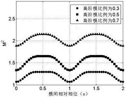
However, theoretical studies have shown that the propagation properties of a beam are only related to the composition of high-power modes in the beam, and have nothing to do with the relative phase between the modes [Rumao Tao, Long Huang, Pu Zhou, Lei Si, and Zejin Liu, “Propagation of high-power fiberlaser with high-order-mode content,"Photonics Research 2015,3(4),192-199]
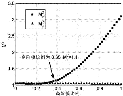
Therefore, traditional M 2 The factor is difficult to reflect the beam quality of the laser exiting the fiber with low numerical aperture and large mode field area

Method used


Image

  • Beam Quality Evaluation Method of Low Numerical Aperture Large Mode Field Area Fiber Laser
  • Beam Quality Evaluation Method of Low Numerical Aperture Large Mode Field Area Fiber Laser
  • Beam Quality Evaluation Method of Low Numerical Aperture Large Mode Field Area Fiber Laser

Examples


Embodiment 1

[0088] See attached Image 6 As shown, the laser beam 1 output from the fiber with low numerical aperture and large mode field area is collimated by the collimation system 2 and then continues to transmit. The light intensity distribution in the near field is measured by a CCD camera 7 at the laser output plane 3 , and the spot data is recorded and processed by a computer 6 . After the laser has transmitted the distance z, use the CCD camera 7 to detect the light intensity distribution of the transmitted beam at the transmitted plane 4, and measure the distance between the transmitted plane 4 and the collimation system. Substitute the light intensity distribution detected by the CCD camera 7 at the laser output plane 3 and the post-transmission plane 4 into formulas (14a)-(14b) and formulas (15a)-(15b) to calculate the beam size. The modified M 2 factor to evaluate the beam quality of the output laser.

Embodiment 2

[0090] See attached Figure 7 As shown, the laser beam 1 output from the optical fiber with low numerical aperture and large mode field area passes through the collimation system 2 and is divided into two parts by the high reflection mirror 73. Most of the reflected laser light, that is, the reflected beam 74, is used to test the laser power, and the transmitted A small part of the laser light, that is, the transmitted light beam 75 is first imaged on the CCD camera 7, and the measured near-field spot is recorded by the computer 6, and then the transmitted light beam 75 is focused on the CCD camera 7 to measure the far-field spot through the focusing optical system 76. The light spot measured by the CCD camera 7 utilizes formulas (14a)-(14b) and formulas (15a)-(15b) to calculate the far-field spot size after the near field, and finally the calculated spot size and the focal length f(z=f) of the focusing system Substituting into formulas (17a)-(17b) to get the modified M 2 fac...


PUM


Abstract

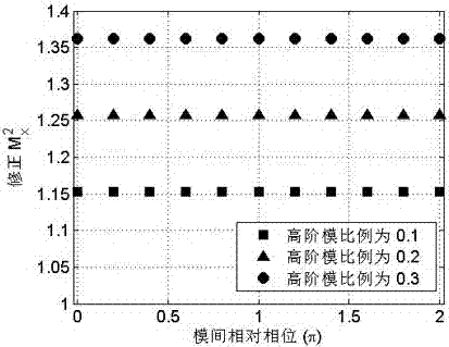
The invention relates to an evaluation method of laser beam quality of a low-numerical aperture large-mode field area fiber. According to the invention, effects on an M2 factor imposed by inter-mode relative phases can be eliminated, so the M2 factor which is only related to inter-mode power proportion but not related to the inter-mode relative phases can be obtained. The M2 factor modified with the method can precisely reflect mode components and laser beam quality of the low-numerical aperture large-mode field area fiber. The closer to 1 the numerical value of the M2 factor is, the better the laser beam quality is. In this way, effects on laser beam quality imposed by the inter-mode relative phases are eliminated, and a disadvantage is overcome that it is hard to evaluate the laser beam quality of the low-numerical aperture large-mode field area fiber via an M2 factor.

Description

technical field [0001] The invention relates to a method for evaluating the beam quality of a fiber laser beam with a low numerical aperture and a large mode field area, in particular to a method using a modified M 2 A method to evaluate the beam quality of low numerical aperture large mode field area fiber laser using the factor definition formula. Background technique [0002] Beam quality is an extremely important parameter in laser application technology. It is a performance index for evaluating laser characteristics in terms of quality. It has very important guiding significance for the design, manufacture, detection and application of lasers. At present, there are many methods to evaluate the beam quality of the laser, such as M 2 Factor, barrel power, Strehl ratio, etc. [Feng Guoying, Zhou Shouhuan, "Discussion on Comprehensive Evaluation of Laser Beam Quality," China Laser, 2009, 36, 1643-1653], where M 2 The factor is defined as the ratio of the product of the spo...

Claims


Application Information

Patent Timeline
Patent Type & Authority Patents(China)
IPC IPC(8): G01M11/02
CPCG01M11/02
Inventor 陶汝茂支冬马阎星冷进勇马鹏飞王小林周朴司磊许晓军陈金宝刘泽金
Owner NAT UNIV OF DEFENSE TECH
Why Eureka
Try Eureka