
Aberration Correction Method of Array High Speed ​​Camera System Based on Digital Speckle

A high-speed camera and digital speckle-related technology, applied in the field of experimental solid mechanics dynamic testing technology and digital image, can solve the problems of many sources of aberration, errors, and difficulty in focusing completely, so as to achieve accurate and universal experimental results The effect of sex and precision

Inactive Publication Date: 2018-04-10
TSINGHUA UNIV
View PDF6 Cites 0 Cited by
  • Summary
  • Abstract
  • Description
  • Claims
  • Application Information

AI Technical Summary

Problems solved by technology

[0003] There are many sources of aberration in the array high-speed camera system. First, it is difficult to ensure that the focus of each CCD is exactly the same. Therefore, even for a fixed-focus lens, the slight difference in focus will cause a scaling error similar to strain; second, the viewing angle The field cannot be guaranteed to be completely consistent, which will introduce errors similar to rigid body displacement; moreover, errors similar to distortion caused by the optical axes of each CCD are not completely parallel

Method used


Image

  • Aberration Correction Method of Array High Speed ​​Camera System Based on Digital Speckle
  • Aberration Correction Method of Array High Speed ​​Camera System Based on Digital Speckle
  • Aberration Correction Method of Array High Speed ​​Camera System Based on Digital Speckle

Examples


Embodiment Construction

[0022] The specific structure, working principle and working process of the present invention will be further described below in conjunction with the accompanying drawings, but the protection scope of the present invention should not be limited by this.

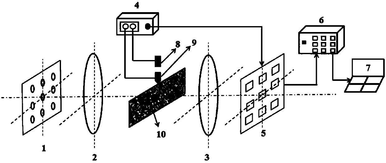
[0023] figure 1 It is a schematic diagram of the structure and principle of the digital array high-speed camera system adopted in the present invention. The system mainly includes: m×n array light source system 1, first imaging lens 2, second imaging lens 3, timing synchronization delay control system 4, m×n An n-array CCD camera system 5, a switch 6 and a computer 7, wherein m≥2, n≥2; the light emitted by the m×n array light source system 1 is refracted by the first imaging lens 2 to become parallel light, and passes through the test piece 10 Then converge through the second imaging lens 3 , and finally the image is received by the m×n array CCD camera system 5 , and the collected image is transmitted to the computer 7 thro...


PUM


Abstract

The invention discloses a digital-speckle-based aberration correction method for an array-type high-speed photography system, and belongs to the field of experimental solid mechanics dynamic testing technologies and digital image technologies. The digital-array-type high-speed photography system comprises an array light source system, an array CCD camera system, a timing sequence synchronization delay control unit, an optical imaging unit, a low-speed drop hammer impact loading unit and the like. Aiming at the inherent aberration problem of the digital-array-type high-speed photography system, digital image aberration generated under coupling of various error factors is analyzed based on the basic method for digital image related processing, iterative correction on the aberration of images collected by CCD cameras at different positions is proposed and completed, the aberration problem caused by focusing and position differences of cameras and other factors is solved, and thus experimental results are more accurate.

Description

technical field [0001] The invention relates to an aberration correction method of an array type high-speed camera system, which belongs to the field of experimental solid mechanics dynamic test technology and digital image technology. Background technique [0002] The combination of high-speed camera technology and photomechanics has played an important role in the experimental dynamic fracture mechanics and the measurement of the dynamic mechanical properties of materials. Although a lot of research has been done on the design and application of the arrayed high-speed camera system, there is a lack of research on the impact of the aberration problem caused by multi-factor coupling. These shortcomings largely hinder the application of this technology in mechanical dynamic testing. development and its application in engineering. It is urgent to propose a simple and effective aberration correction method for the inherent aberration problem of the digital array high-speed cam...

Claims


Application Information

Patent Timeline
Patent Type & Authority Patents(China)
IPC IPC(8): G01N3/00
CPCG01N3/00G01N2203/0647
Inventor 姚学锋王申刘伟杨恒柯玉超
Owner TSINGHUA UNIV
Learn More