Shaft transmission-based engine rotation speed signal simulation system

A technology of engine speed and signal simulation, applied in simulators, general control systems, control/regulation systems, etc., can solve problems such as the inability to effectively verify the correctness of software algorithms, inaccurate transmission ratios, etc., to overcome the uncertainty of transmission ratios , high precision, the effect of preventing injury

Active Publication Date: 2016-05-11
SHANGHAI UNIV OF ENG SCI
View PDF7 Cites 4 Cited by
  • Summary
  • Abstract
  • Description
  • Claims
  • Application Information

AI Technical Summary

Problems solved by technology

[0003] The traditional engine speed signal simulation system uses a belt drive between the crankshaft signal plate and the camshaft signal plate. However, due to the inherent shortcomings of the belt drive, the transmission ratio is not accurate, so the correctness of the software algorithm cannot be effectively verified.

Method used


Image

  • Shaft transmission-based engine rotation speed signal simulation system
  • Shaft transmission-based engine rotation speed signal simulation system
  • Shaft transmission-based engine rotation speed signal simulation system

Examples


Embodiment

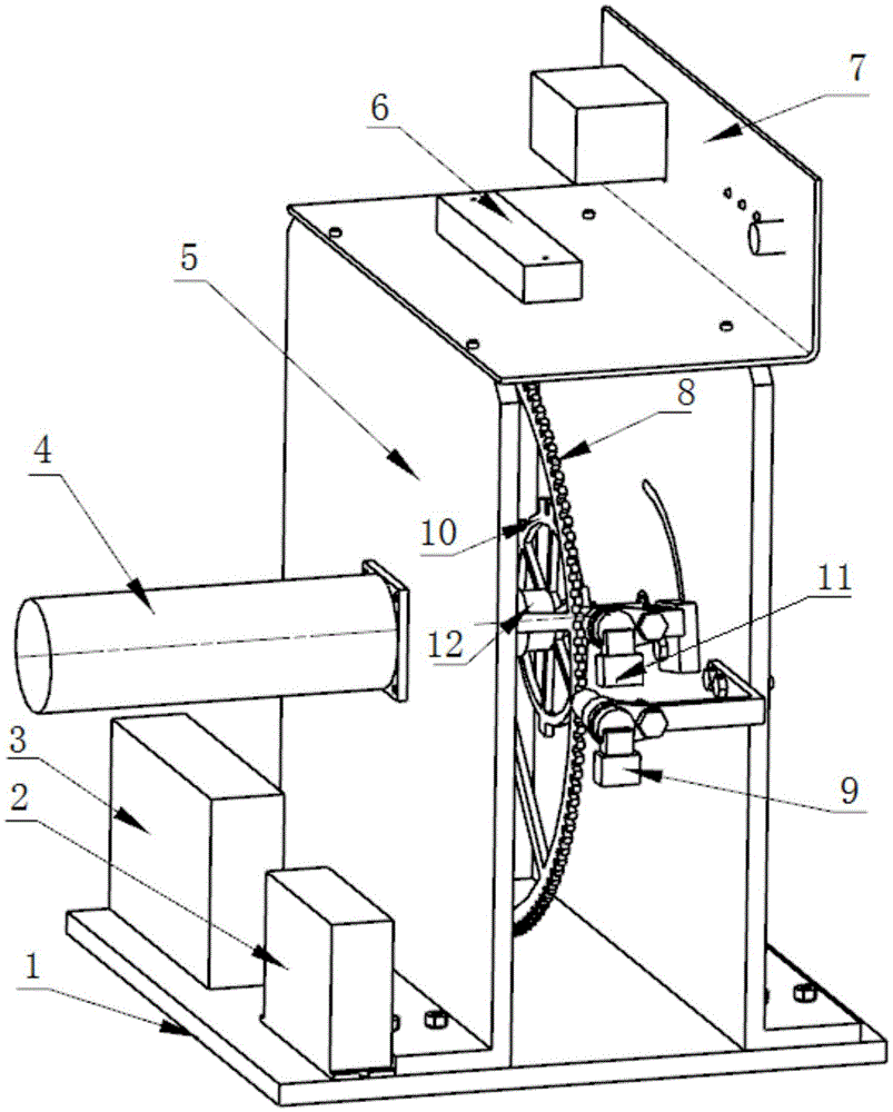
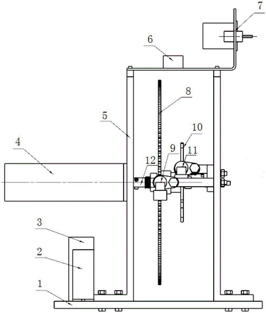
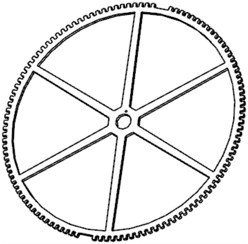
[0026] Such as Figure 1~4 As shown, an engine speed signal simulation system based on shaft transmission includes a mounting base and a drive mechanism installed thereon, a crankshaft signal plate 8, a camshaft signal plate 10, a crankshaft speed sensor 9 and a camshaft speed sensor 11, the The crankshaft speed sensor 9 and the camshaft speed sensor 11 are correspondingly arranged on the sides of the crankshaft signal plate 8 and the camshaft signal plate 10, the system also includes a transmission shaft 12, the drive mechanism is connected to the transmission shaft 12, and the crankshaft signal The disk 8 and the camshaft signal disk 10 are both sleeved on the transmission shaft 12 and fixedly connected with the transmission shaft 12 respectively. The crankshaft speed sensor 9 and the camshaft speed sensor 11 are Hall sensors, which have high measurement accuracy; The driving mechanism drives the transmission shaft 12 to rotate, and then drives the crankshaft signal disk 8 a...


PUM


Abstract

The invention relates to a shaft transmission-based engine rotation speed signal simulation system, which comprises a mounting seat, and a driving mechanism, a crankshaft signal disk, a camshaft signal disk, a crankshaft rotation speed sensor and a camshaft rotation speed sensor arranged on the mounting seat, wherein the crankshaft rotation speed sensor and the camshaft rotation speed sensor are arranged on side surfaces of the camshaft signal disk and the crankshaft signal disk correspondingly. The system also comprises a transmission shaft. The driving mechanism is connected with the transmission shaft; both the crankshaft signal disk and the camshaft signal disk sleeve the transmission shaft and are fixedly connected with the transmission shaft respectively; the driving mechanism drives the transmission shaft to rotate to further drive the crankshaft signal disk and the camshaft signal disk to rotate synchronously; and the crankshaft rotation speed sensor and the camshaft rotation speed sensor detect rotation speed signals of the crankshaft signal disk and the camshaft signal disk respectively. Compared with the prior art, the shaft transmission-based engine rotation speed signal simulation system has the advantages that the structure is simple; the precision is high; the simulation result is closer to an actual condition and the like.

Description

technical field [0001] The invention relates to an engine speed signal simulation system, in particular to an engine speed signal simulation system based on shaft transmission. Background technique [0002] As the structure and control strategy of the engine electronic control system become more and more complex, the difficulty of research and development of the electronic control system and the workload of experiments have greatly increased, and the cost has also increased significantly. The V-type development model has become the mainstream of the engine electronic control unit (ECU) development process. In order to cooperate with the development of ECU software, it is necessary to use the hardware simulation environment to simulate the working state of the engine to verify the correctness of the software algorithm. The engine speed signal is an important signal of the working state of the engine. The specific phase relationship information of the engine crankshaft and cam...

Claims


Application Information

Patent Timeline
Patent Type & Authority Applications(China)
IPC IPC(8): G05B17/02
CPCG05B17/02
Inventor 吴长水李启杰龚元明周建鹏
Owner SHANGHAI UNIV OF ENG SCI
Why Eureka
Try Eureka