Magnetic table of rotary screen printing machine

A technology of rotary screen printing and magnetic table, which is applied to screen printing machines, printing machines, rotary printing machines, etc. It can solve the problems of increasing the load of the belt drive motor, affecting the printing quality, and wearing the printing belt, so as to reduce the Energy consumption, ingenious design concept, and the effect of improving production efficiency

Inactive Publication Date: 2016-05-18
HUNAN JICHANG SILK
View PDF6 Cites 2 Cited by
  • Summary
  • Abstract
  • Description
  • Claims
  • Application Information

AI Technical Summary

Problems solved by technology

At present, the main problem of the magnetic table of the printing machine is that the magnetic force is not enough and uneven, which affects the printing quality. If the magnetic force is to be increased, the current must be increased, but it will generate heat, causing the tank to be deformed by heat, and the coil will be overloaded. , burn out the coil, and because of the poor working environment of the printing machine, there are often garbage on the printing guide belt, and this kind of garbage often accumulates in front of the magnetic table and cannot pass through the magnetic table. After a long time, the printing guide belt will be worn
And because there is sliding friction between the printing guide belt and the magnetic table, the friction resistance is large, and the load on the guide belt drive motor will be increased, and even the motor will be burned.
Many domestic manufacturers have thought of many ways to solve this problem, such as adding cooling devices, but they cannot solve the problem fundamentally.

Method used


Image

  • Magnetic table of rotary screen printing machine
  • Magnetic table of rotary screen printing machine
  • Magnetic table of rotary screen printing machine

Examples


Embodiment Construction

[0019] In order to deepen the understanding of the present invention, the present invention will be further described below in conjunction with examples, which are only used to explain the present invention and do not constitute a limitation to the protection scope of the present invention.

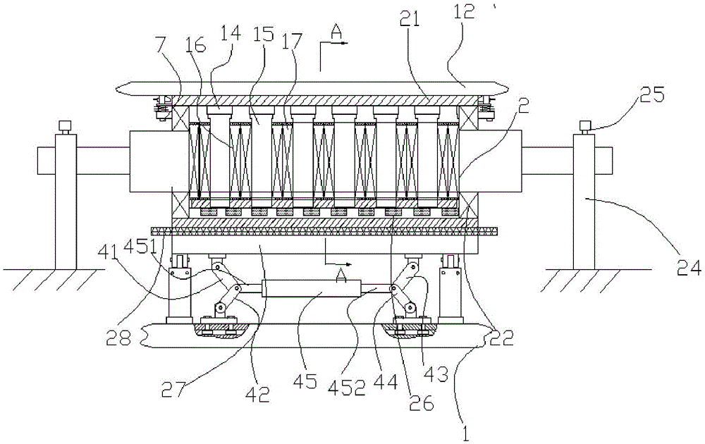
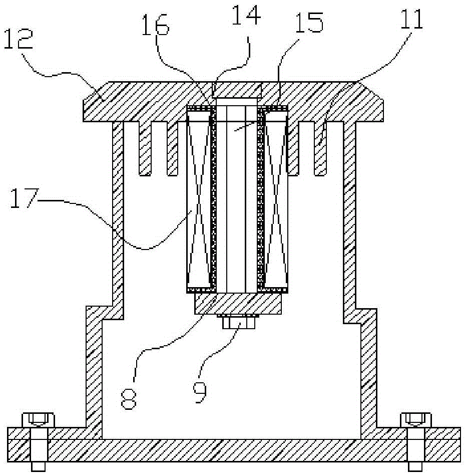
[0020] Such as figure 1 , figure 2 As shown, the magnetic table of the rotary screen printing machine according to the embodiment of the present invention, in order to ensure the convenient positioning of the printed matter on the rotary screen, and at the same time, improve the shock resistance of the magnetic table of the rotary screen printing machine, the magnetic table can be raised as required, In this way, the upper surface of the magnetic table can be close to or in contact with the rotary screen to achieve the best adsorption effect, and the operation is very convenient. In addition, the magnetic table can also be lowered as needed, so that when the magnetic table is magnetic, ...


PUM


Abstract

The invention discloses a magnetic table of a rotary screen printing machine. The magnetic table comprises a tank, a roller, a magnetic table top and a magnetic table base. A plurality of iron core holes are formed in the magnetic table top. An iron core is inserted in each iron core hole in the tank. Each iron core is sleeved with a frame, a coil is wound on each frame, a permanent magnet is arranged on the bottom face of the tank, the two ends of the tank are connected to a support through positioning screws, and the support is fixed to the bottom face. The tank is sleeved with the roller through bearings, the wall of the roller is located between the permanent magnet and a magnetic bar, and the outer wall of the roller makes contact with a printing guide belt. The permanent magnet is fixed to the bottom face of the magnet base with the position capable of being adjusted in the circumferential direction. The magnet base is sleeved with the roller through the bearings, so that on the premise that the permanent magnet and the magnetic bar attract each other, rolling friction is achieved through the roller and the printing guide belt, the friction coefficient between the roller and the printing guide belt is reduced, abrasion is reduced, production efficiency is improved, and energy consumption is reduced.

Description

Technical field: [0001] The invention relates to the technical field of textile machinery, in particular to a magnetic table of a rotary screen printing machine. Background technique: [0002] At present, the magnetic table of the printing machine mainly includes a tank body, a coil, an iron core, and a cylindrical skeleton. The tank is not only the work surface, but also the support of the iron core. The coil is wound on the frame. When the direct current is applied, the coil will generate a magnetic field, and the magnetic circuit will be generated through the iron core. Within a certain length (W=2000-3000, even more than 3000) , Combine multiple coils together to form a magnetic circuit. When working, put the workpiece (magnetic conductor) on the tank, and the magnetic conductor generates a downward magnetic force in the magnetic field. The magnetic force is related to the current, the cross-sectional area of ​​the iron core, and the length of the magnetic circuit: the ...

Claims


Application Information

Patent Timeline
Patent Type & Authority Applications(China)
IPC IPC(8): B41F15/16
CPCB41F15/16
Inventor 吴国强
Owner HUNAN JICHANG SILK
Why Eureka
Try Eureka