Formic acid decomposition apparatus and formic acid decomposition method

A technology of formic acid and decomposition, applied in separation methods, auxiliary devices, chemical instruments and methods, etc., can solve problems such as corrosion, scattering and adhesion, and achieve the effect of improving production efficiency

Active Publication Date: 2016-05-18
ORIGIN CO LTD
View PDF11 Cites 7 Cited by
  • Summary
  • Abstract
  • Description
  • Claims
  • Application Information

AI Technical Summary

Problems solved by technology

[0005] However, formic acid may corrode the chamber material, and the corroded product may become a contamination source in the chamber as a metallic impurity, and may scatter and adhere to the substrate or electronic components mounted on the substrate. Therefore, it is necessary to remove formic acid from the chamber after the reduction treatment is completed.

Method used


Image

  • Formic acid decomposition apparatus and formic acid decomposition method
  • Formic acid decomposition apparatus and formic acid decomposition method
  • Formic acid decomposition apparatus and formic acid decomposition method

Examples


Embodiment

[0098] Hereinafter, although an Example demonstrates this invention more concretely, this invention is not limited to a following Example.

[0099] (experiment method)

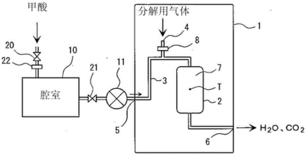
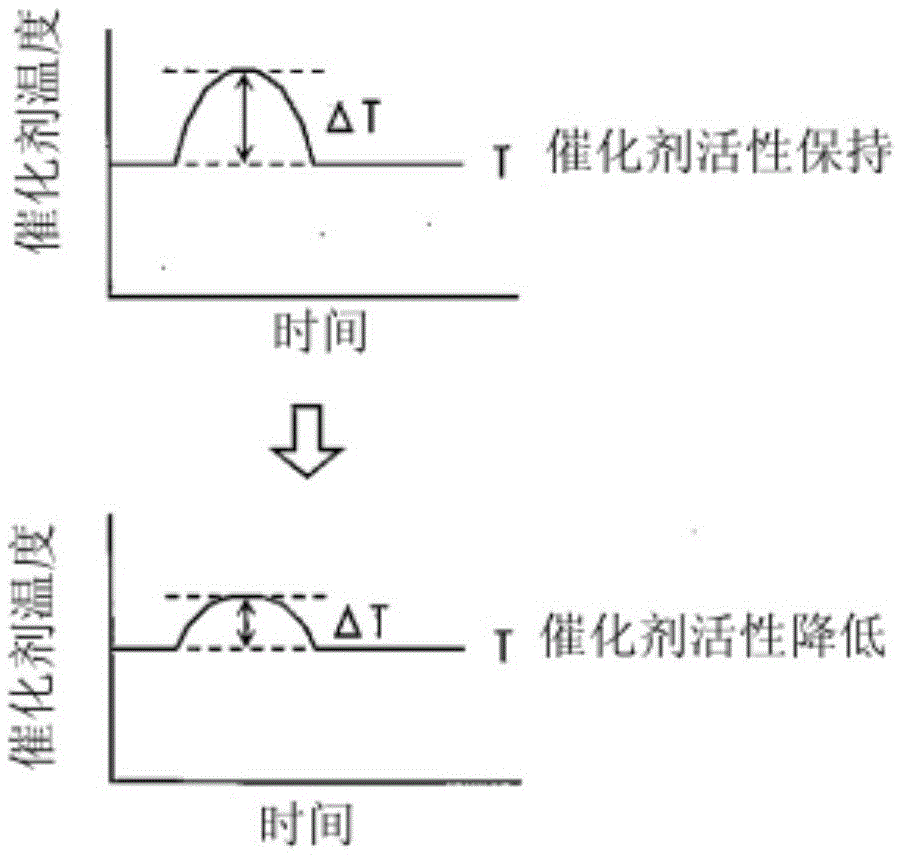
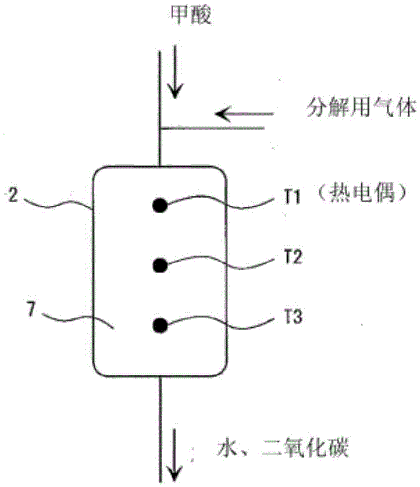
[0100] figure 1 In the shown apparatus, the capacity of the chamber 10 is 20 L, and the test was performed using the apparatus which filled the formic-acid decomposition part 2 with 1 L of catalyst. In addition, if image 3 As shown, in the formic acid decomposition part 2, thermocouples T1, T2, and T3 are provided at three positions of the upstream part, the middle part, and the downstream part of the catalyst layer. These thermocouples are installed at the center of the catalyst layer. As a catalyst, a Pt / alumina catalyst in which 1.8 g / L of Pt (platinum) was attached to granular alumina was used. In order to judge the activity of the catalyst, a part of the catalyst whose activity has been lowered was also used together for a test.

[0101] The test method is as follows. In the state where valve 20 an...

Embodiment 1

[0107] As a catalyst, a Pt / alumina catalyst in which 1.8 g / L of platinum was attached to granular alumina was used. 1 L of the newly prepared catalyst was filled in the formic acid decomposition unit 2 to prepare a catalyst layer, and a test was performed according to the above-mentioned test method (referred to as test (a)).

[0108] Next, prepare 330 ml of catalysts with reduced catalyst activity, fill them into the upper 1 / 3 of the formic acid decomposition unit 2 (the lower 2 / 3 is filled with the freshly prepared catalyst used in the test (a), and perform the test according to the aforementioned test method (As test (b)).

[0109] In addition, prepare the catalyst 330ml that catalyst activity loses completely, fill in the part of the top 1 / 3 of formic acid decomposition part 2 (bottom 2 / 3 is filled with the catalyst that is used for test (a) newly prepared), test according to the aforementioned test method ( Let it be test (c)).

[0110] In tests (a), (b), and (c), chang...


PUM


Abstract

Provided are: a formic acid decomposition apparatus which can dispose of formic acid safely and quickly and determine the activity of a packed catalyst; and a formic acid decomposition method. This formic acid decomposition apparatus is to be used in decomposing formic acid contained in an exhaust gas into water and carbon dioxide, said exhaust gas being discharged from a soldering device in which the reduction treatment of surface oxide film with formic acid has been conducted. The formic acid decomposition apparatus is provided with: a formic acid decomposition unit in which a formic acid decomposition catalyst is packed; a gas introduction pipe for introducing a formic acid-containing gas into the formic acid decomposition unit; and a gas introduction mechanism for introducing oxygen or an oxygen-containing gas into the formic acid decomposition unit. In the formic acid decomposition apparatus, the activity of the catalyst is determined on the basis of catalyst temperature change due to the heat generated in the decomposition reaction of formic acid. This formic acid decomposition method comprises: mixing oxygen or an oxygen-containing gas with a formic acid-containing exhaust gas discharged from a soldering device, in which the reduction treatment of surface oxide film with formic acid has been conducted, at a molar ratio of oxygen to formic acid (oxygen / formic acid) of 1.5 or more; subjecting the mixture to reaction in the presence of a formic acid decomposition catalyst; and thus decomposing the formic acid into water and carbon dioxide.

Description

technical field [0001] The invention relates to a device for decomposing formic acid and a method for decomposing formic acid. Background technique [0002] When forming a solder bump on a semiconductor chip, solder is attached to the pad, then the shape of the solder bump is changed from a mushroom shape to a hemispherical shape, and then it is reflowed and soldered. In the conventional soldering method, in order to form a uniform solder bump, the surface oxide film of the solder was removed with a flux, and the surface of the solder bump was cleaned. [0003] However, in soldering using flux, minute voids (voids) may be formed in solder bumps due to decomposition of flux. These voids not only degrade the electrical and mechanical properties of the formed solder joint, but also damage the planarity of the semiconductor with the solder bump attached, and may also affect subsequent semiconductor bonding steps. Volatile substances of the decomposed flux may contaminate the i...

Claims


Application Information

Patent Timeline
Patent Type & Authority Applications(China)
IPC IPC(8): B01D53/86B01J23/42B23K31/02
CPCB01D53/8668B01D53/8696B01D2251/11B01D2255/1021B01D2255/2092B01D2257/70B23K3/08B01D2257/708
Inventor 小泽直人
Owner ORIGIN CO LTD
Why Eureka
Try Eureka