Device and method for removing ultrafine particles in flue gas of coal boiler

A technology for coal-fired boilers and ultra-fine particles, which is applied to combined devices, separation methods, chemical instruments and methods, etc., can solve the problems of large resistance, complicated actual operation, and many equipment, and achieves increased collision probability, increased agglomeration efficiency, The effect of less steam

Inactive Publication Date: 2016-05-25
HEBEI UNIV OF TECH
View PDF5 Cites 28 Cited by
  • Summary
  • Abstract
  • Description
  • Claims
  • Application Information

AI Technical Summary

Problems solved by technology

[0003] The Chinese patent application number 2013106676615 discloses a device and method for synergistically removing ultrafine particles and trace pollutants from coal-fired boiler flue gas. The method is equipped with an adsorbent pre-injection device and an ultrafine particle agglomeration device in front of the desulfurization equipment , Adsorbent adding device and bag dust removal device, after the desulfurization equipment, a spray cleaning device, a reactant adding device and a wet electrostatic precipitator are arranged in sequence. Large particles and the favorable conditions of increasing the relative humidity of the flue gas make the amount of adsorbent larger, the cost is higher, the actual operation is complicated, and the promotion is not easy
[0004] The Chinese patent with application number 2015104361111 discloses a wet desulfurization tower desulfurization, dust removal, fog removal and water saving process. This process mainly uses devices such as impact cooling chamber and condensation chamber. , the connection of each device is cumbersome, the cost is high, the actual operation is complicated, and the promotion is not easy

Method used


Image

  • Device and method for removing ultrafine particles in flue gas of coal boiler
  • Device and method for removing ultrafine particles in flue gas of coal boiler
  • Device and method for removing ultrafine particles in flue gas of coal boiler

Examples


Embodiment 1

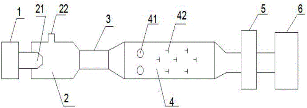
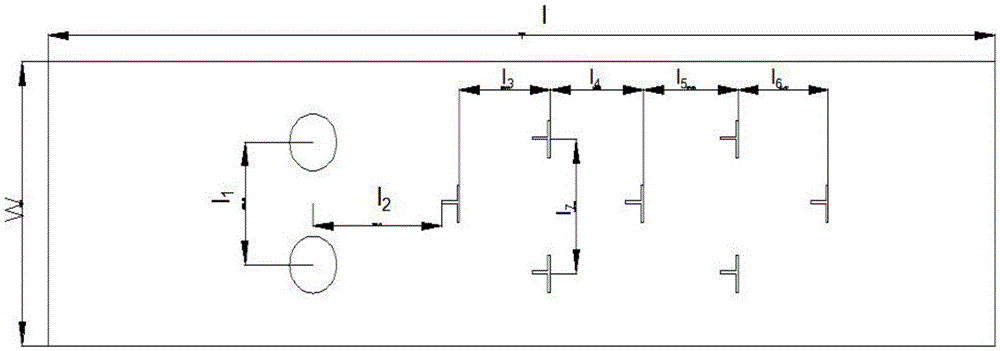
[0045] In this embodiment, the device for removing ultrafine particles in the flue gas of a coal-fired boiler is located after the flue desulfurization equipment 1 at the tail of the coal-fired boiler, and before the electrostatic precipitator 6 of the boiler, and after the desulfurization equipment 1 along the flow direction of the flue gas according to the process flow The smoke steam ejector 2, the steam phase change agglomeration chamber 3, the turbulent flow agglomeration chamber 4 and the mist eliminator 5 are arranged in sequence, and the outlet of the mist eliminator 5 is connected with the electrostatic precipitator 6; the flue gas steam ejector 2 One end connected to the desulfurization equipment 1 is provided with a flue gas inlet 21, and a water vapor inlet 22 is provided on the upper part of the flue gas steam ejector 2; the turbulent agglomeration chamber 4 is provided with a turbulent flow column 41 and a turbulent vortex 42 , the turbulent flow cylinder 41 is ar...


PUM

PropertyMeasurementUnit
particle diameteraaaaaaaaaa

Abstract

The invention relates to a device and a method for removing ultrafine particles in flue gas of a coal boiler. The device is characterized by being sequentially provided with a flue gas steam ejector, a steam phase transformation gathering chamber, a turbulence gathering chamber and a demister behind a desulfuration device along the flow direction of flue gas during a technological process, wherein the outlet of the demister is connected with an electrostatic dust collector; one end, which is connected with the desulfuration device, of the flue gas steam ejector is provided with a flue gas inlet, and the upper part of the flue gas steam ejector is provided with a steam inlet; the turbulence gathering chamber is internally provided with turbulent flow cylinders and turbulent flow vortex sheets; the turbulent flow cylinders are distributed in the front part of the turbulence chamber, and a plurality of turbulent flow vortex sheets are distributed at equal intervals behind the turbulent flow cylinders in a staggered manner; one end of the turbulence chamber is connected with the outlet of the steam phase transformation gathering chamber, and the other end of the turbulence chamber is connected with the inlet of the demister.

Description

technical field [0001] The invention relates to the technical field of dedusting devices, in particular to a device and method for removing ultrafine particles from flue gas of a coal-fired boiler. Background technique [0002] Coal resources are one of the most important fossil fuels in my country, with abundant reserves. The energy structure dominated by thermal power will not change in a short period of time. The dusty flue gas produced by coal burning is one of the main sources of suspended particulate matter in the atmosphere. These particles drift into the atmosphere from traditional equipment (electrostatic precipitator, wet precipitator, mechanical precipitator, etc.), which is very harmful to the human body and the atmospheric environment. Most coal-fired power plants in my country are equipped with high-efficiency dust removal devices, which can remove more than 99% of the mass of smoke and dust, and can basically remove particles larger than 10 μm, but for PM 10 ...

Claims


Application Information

Patent Timeline
Patent Type & Authority Applications(China)
IPC IPC(8): B01D50/00B03C3/017
CPCB01D50/00B01D2258/0283B03C3/017
Inventor 陈占秀张书斌杨历刘联胜王志强葛明慧
Owner HEBEI UNIV OF TECH
Why Eureka
Try Eureka