Polyurea spraying equipment and spraying method and corresponding polyurea composite waterproof layer mechanism

A technology of spraying equipment and waterproof layer, which is applied in the direction of coating, liquid coating device on the surface, spraying device, etc. It can solve the problems of only intermittent suction, intermittent spraying, difficult operation, difficult operation, etc., to achieve The spraying method is simple and easy, highlighting the effect of self-healing performance and scientific structure

Active Publication Date: 2016-05-25
SHANDONG LECRON CONSTR ENERGY SAVING TECH CO LTD
View PDF9 Cites 7 Cited by
  • Summary
  • Abstract
  • Description
  • Claims
  • Application Information

AI Technical Summary

Problems solved by technology

[0005] The Chinese invention patent with the publication number CN104324628A discloses a static mixing device used in the preparation process of two-component polyurea, which adopts synchronous double plunger push rods, which better solves the problem of the synchronization of the A lifting pump and the B lifting pump. Requirements, but because of the same single-cylinder piston pump used, it can only absorb and spray materials intermittently. When the material is sucked, stop spraying, and materials A and B are easy to polymerize and block in the mixing tube (5)
For this reason, it is still difficult to operate
[0006] Imported polyurea spraying equipment has the same basic structure as domestic equipment except for the addition of precision electronic control devices. The operation is complicated and the price is high, which domestic construction teams cannot afford.
The existing domestic polyurea spraying equipment cannot be used by workers without three or five years of practical experience
[0007] Polyurea spraying is in the ascendant, but it is difficult to operate and easy to damage. Existing polyurea spraying equipment has become a bottleneck restricting the development and application of polyurea spraying

Method used


Image

  • Polyurea spraying equipment and spraying method and corresponding polyurea composite waterproof layer mechanism
  • Polyurea spraying equipment and spraying method and corresponding polyurea composite waterproof layer mechanism
  • Polyurea spraying equipment and spraying method and corresponding polyurea composite waterproof layer mechanism

Examples


Embodiment approach 1

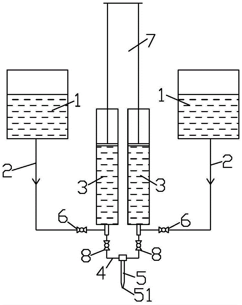
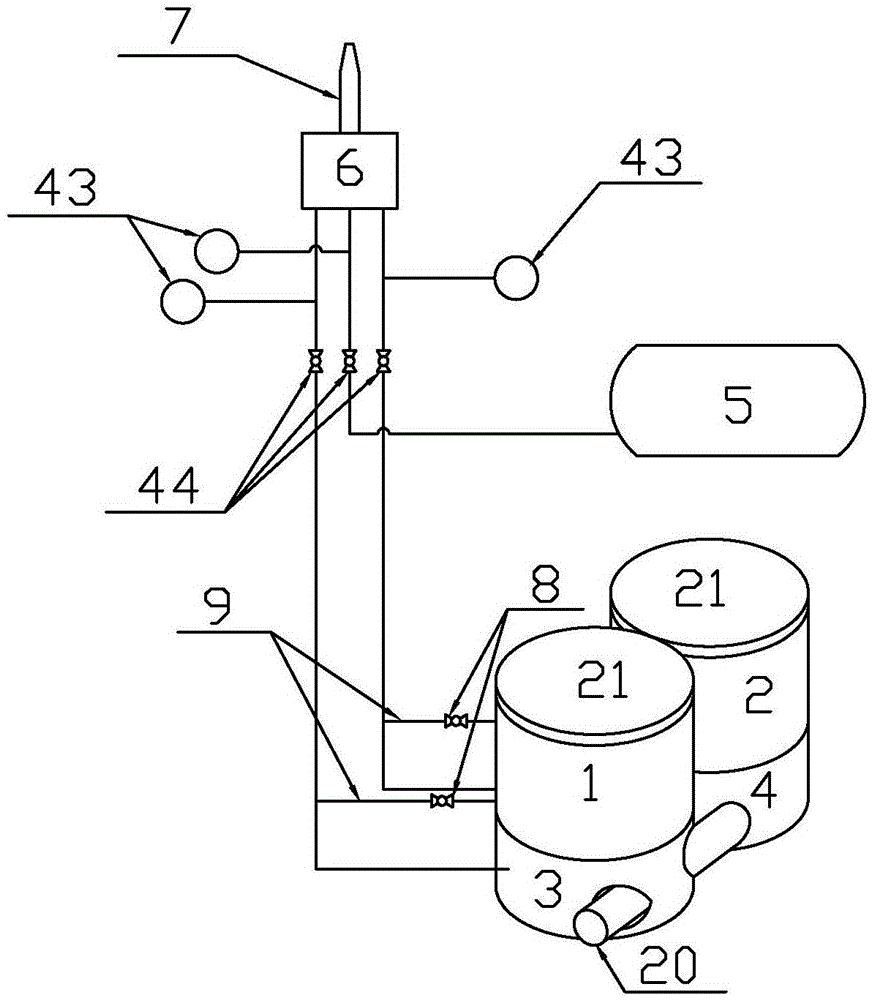
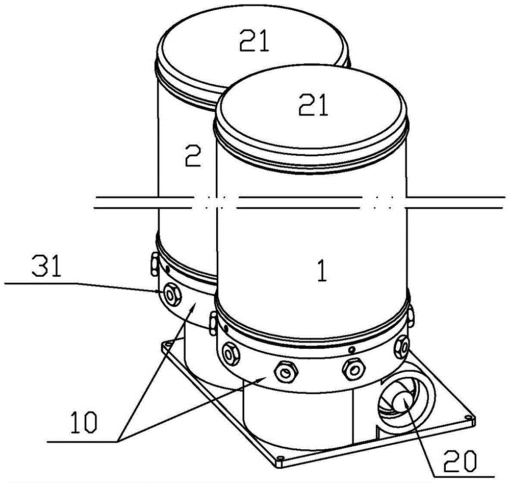
[0054] Implementation mode one: if Figure 2-9 As shown, the polyurea spraying equipment includes A material tank 1, B material tank 2, A material lifting pump 3, B material lifting pump 4, compressed air tank 5 and spray gun 6. The A lifting pump 3, the B lifting pump 4, and the compressed air tank 5 are respectively provided with an inlet and an outlet, and the spray gun 6 is provided with three inlets and a nozzle 7, and the three inlets are respectively connected with the A lifting pump 3 through a hose. The outlet of B, the outlet of B lifting pump 4 and the outlet of compressed gas tank 5 link to each other.

[0055] Such as figure 2 As shown, the inlet of A lifting pump 3 and the inlet of B lifting pump 4 are respectively connected to A material barrel 1 and B material barrel 2; the inlet of compressed air tank 5 is connected to a compressed air source or an air compressor (not shown in the figure) ), A and B lifting pumps 1 and 2 are equipped with a return regulatin...

Embodiment approach 2

[0065] Implementation mode two: if Figure 10-13 As shown, the outlet holes at the outer ends of each plunger chamber 11 are interconnected by passages 32 . Each plunger cavity 11 is a stepped hole with a large outside and a small inside. Each plunger cavity 11 is fixed with a plunger sleeve 28, and the plungers 12 are inserted in the inner end of the plunger sleeve 28 one by one. The outer end of the plunger sleeve 28 is also provided with an outlet hole and a one-way valve mechanism 29. Under the control of the one-way valve mechanism 29, the outlet hole is unidirectionally connected with the outlet hole at the outer end of the corresponding plunger chamber 11.

[0066] The middle section of the plunger sleeve 28 has an inlet hole opposite to the feed hole 13 of the corresponding plunger chamber 11, a circular boss 30 is arranged between the inlet hole and the outlet hole, and a circular boss 30 is arranged on the outlet hole at the outer end of each plunger chamber 11. The...

Embodiment approach 3

[0069] Implementation mode three: if Figure 14 As shown, an anti-deviation device is also provided on the flexible pipe between the A and B lifting pumps 3, 4 and the spray gun 5, and the anti-deviation device includes a hollow housing 33, and the middle of the hollow housing 33 One side is provided with fixed dividing plate 34, and the other side is provided with movable dividing plate 35, and the opposite surface end between movable dividing plate 35 and fixed dividing plate 34 all has arc-shaped notch, is sandwiched between the two. Rotating seal column 36, fixed dividing plate 34, turnable sealing column 36 and movable dividing plate 35 divide the interior of hollow housing 33 into a left secret chamber and a right secret chamber which are not communicated with each other. A chute is formed on the opposite side, and the movable partition 35 is arranged in the chute, and is equipped with a knob 46 for adjusting the clamping degree of the movable partition. By adjusting the ...


PUM


Abstract

The invention relates to polyurea spraying equipment and spraying method and a corresponding polyurea composite waterproof layer mechanism. By means of existing polyurea spraying equipment, uneven material distribution is caused easily. Therefore, the polyurea spraying equipment comprises material buckets A, material buckets B, material lifting pumps A, material lifting pumps B and the like, each material lifting pump A comprises a pump body, N plunger cavities are formed in the inner wall of the center of each pump body along the circumference, the inner side end of each plunger cavity is provided with a plunger, the outer side end of each plunger cavity is provided with an outlet, all the outlets are converged into outlets of the material lifting pumps A, all inner end column heads are connected to the outer circumferences of round pushing sleeves A all the time, the round pushing sleeves are arranged on eccentric wheels A in a sleeving mode through bearings, and each eccentric wheel A is fixed to a shaft A; the material lifting pumps A and the material lifting pumps B are identical, and N is a positive integer which is greater than three. The shafts A and shafts B are coaxially driven, and the material buckets A and the material buckets B are each provided with an electric heating device and a stirring device. The invention further relates to the polyurea spraying method and the polyurea waterproof layer mechanism. The polyurea spraying equipment and spraying method and the corresponding polyurea composite waterproof layer mechanism have the advantages that uneven material distribution is not caused, and the polyurea spraying equipment and spraying method and the corresponding polyurea composite waterproof layer mechanism are applicable to various occasions where polyurea needs to be sprayed.

Description

technical field [0001] The invention relates to a polyurea spraying equipment, a spraying method and a corresponding polyurea composite waterproof layer mechanism. Background technique [0002] Polyurea elastomer waterproof material is a two-component elastomer material formed by the polymerization of components A and B. It can be used alone or combined with other materials as waterproof coatings on the surface of concrete or other substrates, linings, and medium-resistant materials. Forms hard coating films of different thicknesses and can be applied to various occasions and to treat suitable substrates. [0003] However, the polyurea elastomer waterproof material needs to be sprayed with special spraying equipment. The commonly used domestic polyurea spraying equipment includes A bucket, B bucket, A pump, B pump, compressed air tank and spray gun, and A bucket. The pump, B lifting pump, and compressed air tank are respectively equipped with inlets and outlets. The spray g...

Claims


Application Information

Patent Timeline
Patent Type & Authority Applications(China)
IPC IPC(8): B05B9/047B05D5/00B05D7/24B05D7/00
CPCB05B9/047B05D5/00B05D7/24B05D7/52B05D2518/00B05D2420/02
Inventor 魏中传刘开涛常双喜朱仲波赵亮
Owner SHANDONG LECRON CONSTR ENERGY SAVING TECH CO LTD
Why Eureka
Try Eureka