Manipulator movement method and system

A motion system and manipulator technology, applied in the direction of manipulators, program-controlled manipulators, manufacturing tools, etc., can solve problems such as unproposed motion trajectories, achieve the effects of improving flexibility, improving production efficiency, and saving time

Active Publication Date: 2017-11-17
SHENZHEN HUACHENG IND CONTROL
View PDF5 Cites 0 Cited by
  • Summary
  • Abstract
  • Description
  • Claims
  • Application Information

AI Technical Summary

Problems solved by technology

Although this scheme proposes a control method for the movement trajectory of the manipulator, it is aimed at the movement trajectory of each channel of the solar energy, and does not propose an effective movement trajectory, so that the movement of the manipulator can achieve higher production efficiency

Method used


Image

  • Manipulator movement method and system
  • Manipulator movement method and system
  • Manipulator movement method and system

Examples


Embodiment 1

[0069] Please refer to Figure 2-3 , Embodiment 1 of the present invention is: a kind of manipulator movement method, is used for controlling the motion between manipulator loading and unloading, comprises the following steps:

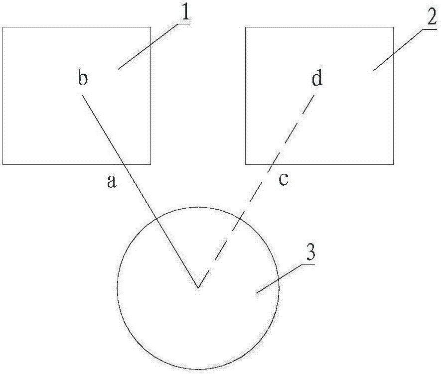
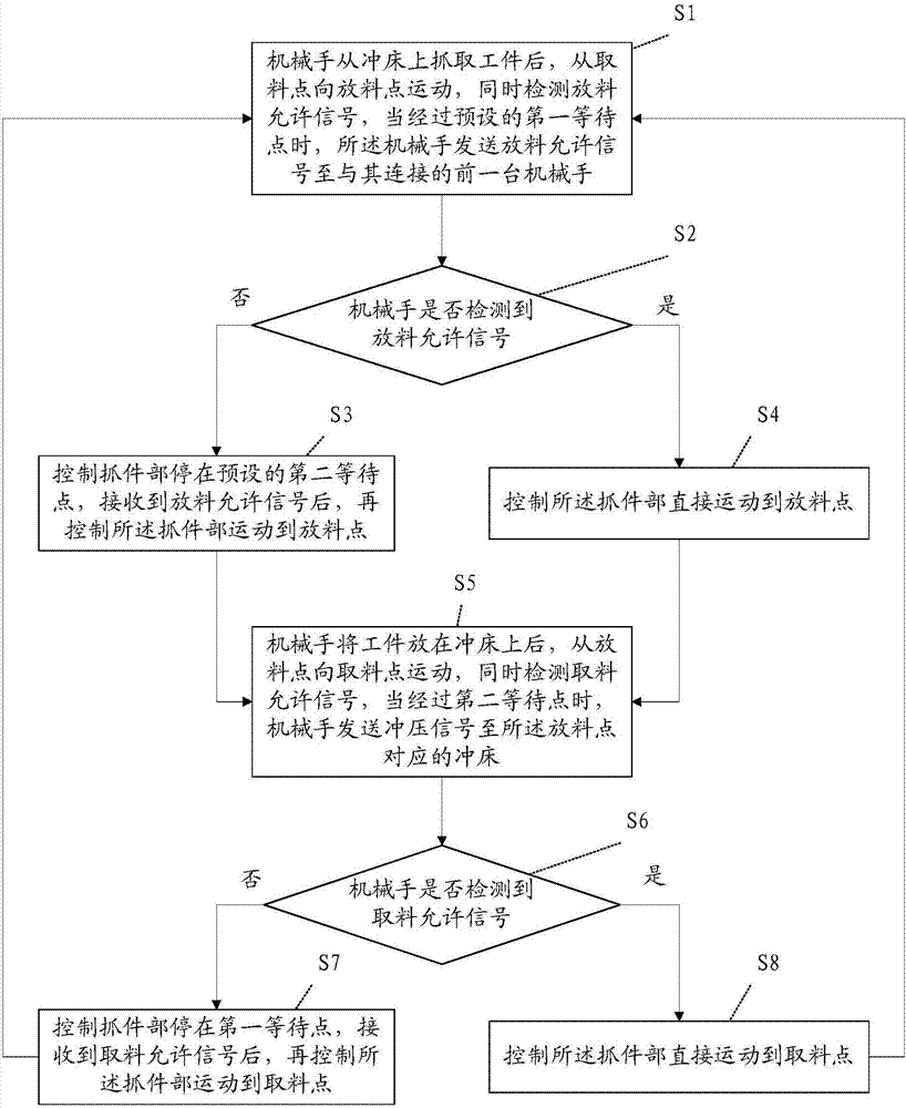
[0070] S1: After the manipulator grabs the workpiece from the punch corresponding to the pick-up point, it moves from the pick-up point to the discharge point, and at the same time detects the discharge permission signal. When passing the preset first waiting point, the manipulator sends the discharge Allows the signal to the previous robot connected to it.

[0071] S2: Judging whether the manipulator detects the material discharging permission signal, if not, execute step S3, and if yes, execute step S4.

[0072] S3: Control the gripping part to stop at the preset second waiting point, and control the gripping part to move from the second waiting point to the material discharging point when the manipulator receives a material discharging permission s...

Embodiment 2

[0083] Please refer to Figure 6-7 , the second embodiment of the present invention is a manipulator motion system corresponding to the above method, including

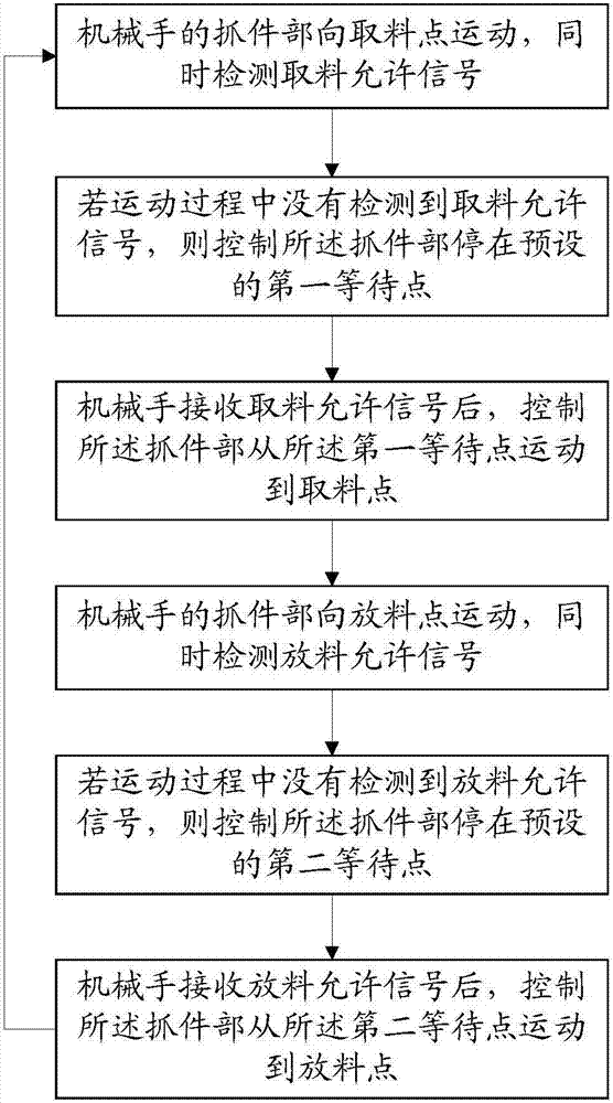
[0084] The first detection module 101 is used for the gripping part of the manipulator to move to the material retrieval point and simultaneously detect the material retrieval permission signal;

[0085] The first control module 102 is configured to control the gripping part to stop at the preset first waiting point if no material retrieving permission signal is detected during the movement;

[0086] The second control module 103 is used to control the gripping part to move from the first waiting point to the material picking point after the manipulator receives the material picking permission signal;

[0087] The second detection module 104 is used for the gripping part of the manipulator to move to the discharge point and simultaneously detect the discharge permission signal;

[0088] The third control module 105 ...


PUM


Abstract

The invention discloses a moving method and system for a mechanical arm. The method includes the steps that a part grasping part of the mechanical arm moves to a fetching point, and meanwhile fetching enabling signals are detected; if no fetching enabling signal is detected in the moving process, the part grasping part is controlled to stop at a first preset holding point; after the mechanical arm receives the fetching enabling signals, the part grasping part is controlled to move to the fetching point from the first holding point; the part grasping part of the mechanical arm moves to a discharging point, and meanwhile discharging enabling signals are detected; if no discharging enabling signal is detected in the moving process, the part grasping part is controlled to stop at a second preset holding point; after the mechanical arm receives the discharging enabling signals, the part grasping part is controlled to move to the discharging point from the second holding point; after discharging is completed, the mechanical arm continues to execute the step that the part grasping part of the mechanical arm is moved to the fetching point. The mechanical arm conducts detection while moving, the flexibility of control over the mechanical arm is improved, time can be effectively saved, and production efficiency is improved.

Description

technical field [0001] The invention relates to the field of punch manipulators, in particular to a manipulator movement method and system thereof. Background technique [0002] With the improvement of the degree of automation in the industrial field, the use of manipulators has also been promoted for punching and unloading. The stamping production line is often composed of several punching machines. After processing the blanks through several consecutive stamping processes, they are made into qualified products. The first manipulator is responsible for taking out the workpiece from the previous punching machine and putting it into the next punching machine for the next stamping process. [0003] Such as figure 1 As shown, the current movement process of manipulator loading and unloading is as follows: manipulator 3 stops at point a to take material and waits for material; Rotate from point a to point c and wait for material discharge; when there is no material in the seco...

Claims


Application Information

Patent Timeline
Patent Type & Authority Patents(China)
IPC IPC(8): B25J9/16
CPCB25J9/1628
Inventor 孙毅董改田张卫锋冷俊苗立晓
Owner SHENZHEN HUACHENG IND CONTROL
Why Eureka
Try Eureka