
Cleaning device for spinning machine

A technology for cleaning devices and textile machinery, which is applied to cleaning devices for processing textile materials, textiles, textiles and papermaking, etc. It can solve the problems of poor cleaning effect and waste of manpower, and achieve high work efficiency, strong practicability, and remarkable cleaning effect Effect

Active Publication Date: 2016-05-25
南通景群纺织品有限公司
View PDF5 Cites 10 Cited by
  • Summary
  • Abstract
  • Description
  • Claims
  • Application Information

AI Technical Summary

Problems solved by technology

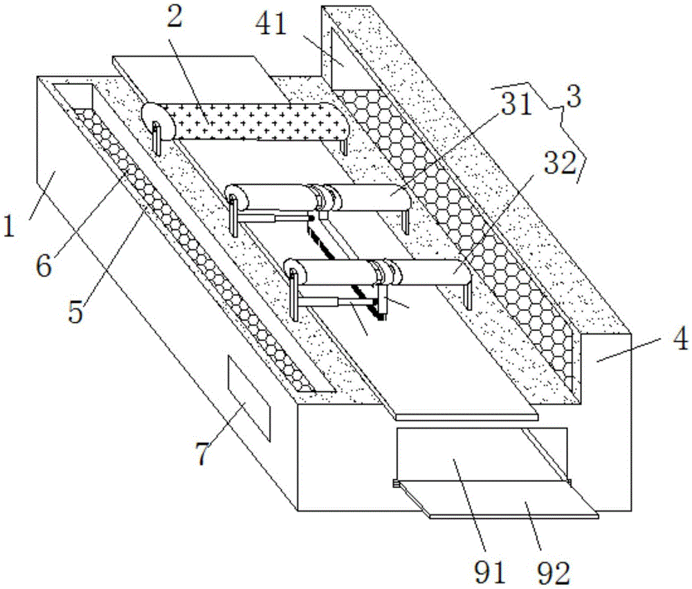
[0002] Textile machinery is usually classified according to the production process: spinning equipment, weaving equipment, printing and dyeing equipment, finishing equipment, chemical fiber spinning equipment, reeling equipment and non-woven fabric equipment, spinning equipment is divided into processing short fiber and processing long fiber Two types, cotton and cotton-type chemical fibers are short fibers, and wool, hemp, silk and their blended chemical fibers are long fibers. The difference between textile machinery and general processing machinery is that its mechanical parts are easy to accumulate due to a large amount of contact with fabrics and fibers. There are a lot of fibers, and it is common to generate dust during work. The existing textile machines generally need to remove the dust during work, which wastes a certain amount of manpower, and the removal effect is poor.

Method used


Image

  • Cleaning device for spinning machine
  • Cleaning device for spinning machine
  • Cleaning device for spinning machine

Examples


Embodiment Construction

[0012] The following will clearly and completely describe the technical solutions in the embodiments of the present invention with reference to the accompanying drawings in the embodiments of the present invention. Obviously, the described embodiments are only some, not all, embodiments of the present invention. Based on the embodiments of the present invention, all other embodiments obtained by persons of ordinary skill in the art without making creative efforts belong to the protection scope of the present invention.

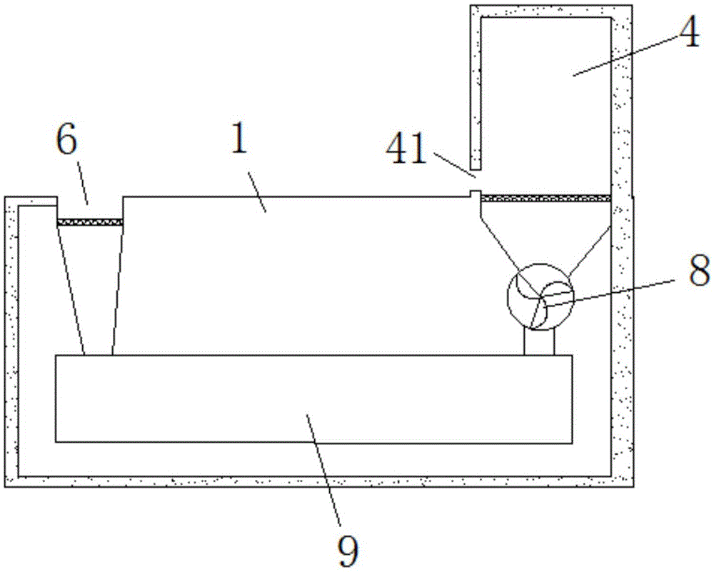
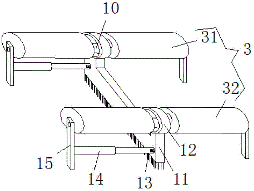
[0013] see Figure 1-3 , the present invention provides a technical solution: a textile machinery cleaning device, including a workbench 1, a cleaning device 3, an ash inlet chamber 4, a collection chamber 9 and a fixing member 15, and the inner cavity of the workbench 1 is provided with a collection chamber 9. The front end of the work 1 is provided with an ash outlet 91 connected to the collection chamber 9, and the lower end of the ash outlet 91 is hinged t...


PUM


Abstract

The invention discloses a cleaning device for a spinning machine. The cleaning device comprises a workbench, a sweeping device, an ash intake cavity, a colleting cavity and a fixing part. The collecting cavity is arranged in the inner cavity of the workbench. A groove is formed in the left end of the upper portion of the workbench. The sweeping device and a cleaning roller are arranged in the middle of the upper portion of the workbench. The sweeping device comprises a first fixing shaft and a second fixing shaft. A fixing rod is arranged in the middle of each of the first fixing shaft and the second fixing shaft. A sweeping plate is arranged at the lower ends of the first fixing shaft and the second fixing shaft. Two ends of the upper portion of the sweeping plate are respectively provided with clamp rings corresponding to the fixing rods. A brush is arranged at the lower end of the sweeping plate. The left side of the sweeping plate is connected with the fixing part through a telescopic rod. The ash intake cavity is arranged in the right end of the upper portion of the workbench. The lower end of the inner cavity of the ash intake cavity is connected with one end of an exhaust fan through a pipeline. The cleaning device is novel in structure, high in practicality, convenient to use and evident in cleaning effect.

Description

technical field [0001] The invention relates to the technical field of textile machinery cleaning devices, in particular to a textile machinery cleaning device. Background technique [0002] Textile machinery is usually classified according to the production process: spinning equipment, weaving equipment, printing and dyeing equipment, finishing equipment, chemical fiber spinning equipment, reeling equipment and non-woven fabric equipment, spinning equipment is divided into processing short fiber and processing long fiber Two types, cotton and cotton-type chemical fibers are short fibers, and wool, hemp, silk and their blended chemical fibers are long fibers. The difference between textile machinery and general processing machinery is that its mechanical parts are easy to accumulate due to a large amount of contact with fabrics and fibers. A large amount of fibers, and it is common to generate dust during work. Existing textile machines generally need to remove dust during w...

Claims


Application Information

Patent Timeline
IPC IPC(8): D01H11/00D02J7/00D03J1/00D04B35/32D06B23/30
CPCD01H11/005D02J7/00D03J1/002D04B35/32D06B23/30
Inventor 潘阿海
Owner 南通景群纺织品有限公司
Learn More