
Axial vibration crawl device

A technology of axial vibration and crawler, which is applied in drilling equipment, drilling equipment and methods, earthwork drilling and production, etc. It can solve the problems of drilling tool assembly retreating and affecting drilling efficiency, etc., and achieves the effect of simple structure

Active Publication Date: 2016-05-25
YANSHAN UNIV
View PDF5 Cites 1 Cited by
  • Summary
  • Abstract
  • Description
  • Claims
  • Application Information

AI Technical Summary

Problems solved by technology

The other part of the force that deviates from the direction of the drill bit will cause the drill tool assembly to retreat slightly, which will affect the drilling efficiency

Method used


Image

  • Axial vibration crawl device

Examples


Embodiment Construction

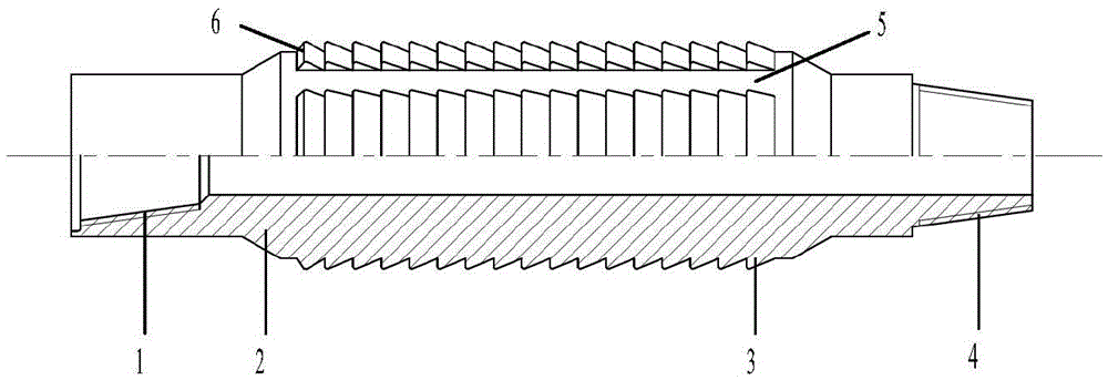
[0013] exist figure 1 In the schematic diagram of the axial vibrating crawler shown, one end of the body 2 is connected to the female buckle 1, the other end of the body is connected to the male buckle 4, and the outer surface of the body is uniformly provided with 6 annular teeth 3 of equal size in the axial direction. Each annular tooth is provided with equal-sized sand dredging grooves 5; the section of each annular tooth is a right-angled triangle, and the right-angled side faces the side of the box, and the section of the first annular tooth 6 on the side of the box is Double bevel.

[0014] This tool is connected to the axial vibration generator through threads, and should be used selectively according to specific working conditions.


PUM


Abstract

The invention relates to an axial vibration crawl device which comprises a crawl device body, a male buckle and a female buckle, wherein 4-10 annular teeth equal in size are longitudinally and uniformly arranged on the outer surface of the crawl device body; sand guide grooves equal in size are uniformly formed in each annular tooth; each annular tooth has a right triangular cross section, and the right-angle side of each annular tooth faces the female buckle; the first annular tooth close to the female buckle side has a double bevel cross section. The axial vibration crawl device is simple in structure, and can prevent counter motion of a drill column and accumulation of rock fragments.

Description

technical field [0001] The invention belongs to the technical field of machinery, in particular to an oil and gas well drilling tool. Background technique [0002] In recent years, the exploration and development technologies for horizontal wells, extended-reach wells and other complex well structure wells have become more and more mature. Due to the large inclination angle, the large pressure difference between the wellbore fluid column and the formation, and the accumulation of cuttings, the frictional resistance of the drill string is relatively large, resulting in the obstruction of the drill pressure transmission, the reduction of the ROP, and the wear of the drill string and casing. serious problem. Experts and scholars at home and abroad have developed axial vibration anti-friction tools. The drill string produces small axial vibrations, which convert the static friction between the drill string and the well wall into dynamic friction in the axial direction, which ca...

Claims


Application Information

Patent Timeline
Patent Type & Authority Applications(China)
IPC IPC(8): E21B7/20E21B17/10
CPCE21B7/20E21B17/1085
Inventor 李子丰宋广明张洪超
Owner YANSHAN UNIV
Learn More