Device for measuring frequency response characteristic parameter of light wave component

A technology of frequency response and characteristic parameters, applied in the direction of measuring devices, measuring electrical variables, spectrum analysis, etc., can solve the problems of complex operation, bulky, inconvenient to carry, etc., to improve strength and frequency stability, improve stability and Reliability, the effect of reducing wavelength chirp

Inactive Publication Date: 2016-05-25
THE 41ST INST OF CHINA ELECTRONICS TECH GRP
View PDF6 Cites 21 Cited by
  • Summary
  • Abstract
  • Description
  • Claims
  • Application Information

AI Technical Summary

Problems solved by technology

The existing test technology mainly uses a test system built by a variety of special test instruments. This test method is complex to operate. Different types of light wave devices need to be familiar with different types of test instruments. The test system is bulky, complicated to operate, and extremely inconvenient to carry.
[0009] To sum up, the current measurement method has the disadv

Method used


Image

  • Device for measuring frequency response characteristic parameter of light wave component
  • Device for measuring frequency response characteristic parameter of light wave component
  • Device for measuring frequency response characteristic parameter of light wave component

Examples


Embodiment 1

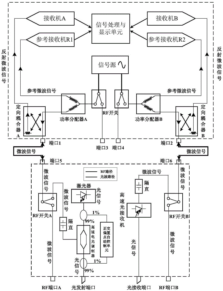
[0039] Optical test: The microwave signal sent by the microwave signal source passes through the power divider A, and one path is used as a reference microwave signal to be received by the reference receiver; the other path passes through the directional coupler A and is transmitted from port 1 to port 5, and then the microwave signal is transmitted through the RF switch A To the electro-optical modulator, high-frequency modulation is performed on the light wave signal, and the light wave signal modulated by microwave is output from the light emitting port. The measured light wave signal is converted into a microwave signal, and the microwave signal is transmitted to the port 6 through the RF switch B, and then transmitted to the microwave receiver B through the port 2 and the directional coupler.

Embodiment 2

[0041] Electrical test: The microwave signal sent by the microwave signal source passes through the power divider A, and one path is used as a reference microwave signal to be received by the reference receiver; the other path passes through the directional coupler A and is transmitted from port 1 to port 5, and then the microwave signal is transmitted through the RF switch A to the RF port A, and then the microwave signal is received by the RF port B after passing through the DUT, the microwave signal is transmitted to the port 6 through the RF switch B, and then transmitted to the microwave receiver B through the port 2 and the directional coupler.

Embodiment 3

[0043] Electro-optic test: The microwave signal sent by the microwave signal source passes through the power divider A, and one path is received by the reference receiver as a reference microwave signal; the other path is transmitted from port 1 to port 5 through the directional coupler A, and then the microwave signal is transmitted to the The RF port A passes through the DUT, and the light wave signal generated by the DUT is received by the light wave receiving port. The light wave signal is converted into a microwave signal by the high-speed optical receiver, and the microwave signal is transmitted to the port through the RF switch B. 6, and then transmitted to microwave receiver B through port 2 and directional coupler.


PUM


Abstract

The invention discloses a device for measuring the frequency response characteristic parameter of a light wave component. The device comprises a signal separation unit, a signal processing unit, a multichannel amplitude phase frequency mixing reception unit, an RF test unit and a high-frequency optical carrier wave signal generation unit; and a signal source generates a high-frequency modulated electric microwave signal, the signal separation unit separates the high-frequency modulated electric microwave signal into a reference signal and an input signal, and the reference signals and the input signal are received by the multichannel amplitude phase frequency mixing reception unit. Electric-optical, optical-electrical, optical-optical and electric-electric test functions are integrated in the device, the device is convenient to carry and highly integrated, and the frequency response characteristics of different light wave devices can be tested rapidly and accurately.

Description

technical field [0001] The invention relates to a device for measuring frequency response characteristic parameters of light wave components. Background technique [0002] With the rapid development of the Internet, cloud computing and big data platforms have emerged as the times require, and the global demand for information has increased sharply, prompting the development of optical communication technology in the direction of high speed and large capacity. 40G high-speed optical fiber communication system has become a research hotspot and entered practical application Therefore, the frequency response characteristic parameter measurement device for high-speed optoelectronic and electro-optical devices needs to be developed urgently. In a high-speed optical transmission system, core optical components such as lasers, electro-optic modulators, photodetectors, and optical amplifiers are the core devices that affect the quality of signal communication. The bias and bandwidth ...

Claims


Application Information

Patent Timeline
IPC IPC(8): G01R23/00
Inventor 魏石磊张志辉张爱国李宝瑞王瑞霞王广彪
Owner THE 41ST INST OF CHINA ELECTRONICS TECH GRP
Why Eureka
Try Eureka