
Cell test method and device

A technology of false pressure testing and flexible circuit boards, which is applied in the direction of measuring devices, semiconductor/solid-state device testing/measurement, and electrical measurement. Conducive to product quality control and the effect of solving placement problems

Active Publication Date: 2016-05-25
WUHAN CHINA STAR OPTOELECTRONICS TECH CO LTD
View PDF6 Cites 9 Cited by
  • Summary
  • Abstract
  • Description
  • Claims
  • Application Information

AI Technical Summary

Problems solved by technology

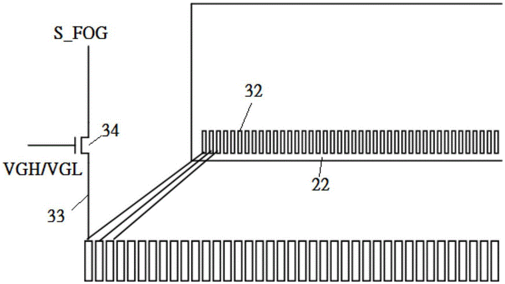
[0004] In order to solve the problem that the above-mentioned dummy pressure test board cannot be placed, an embodiment of the present invention proposes a dummy pressure test (CellTest) method, which includes the following steps: When greater than a critical value, additionally add a false pressure test board required for the false pressure test at the FOG end of the semi-finished product board; place an alignment mark at the false pressure test board; and use a charge coupled device (chargecoupleddevice) to carry out a dummy pressure alignment program

Method used


Image

  • Cell test method and device
  • Cell test method and device
  • Cell test method and device

Examples


Embodiment Construction

[0015] The following descriptions of the various embodiments refer to the accompanying drawings to illustrate specific embodiments in which the present invention can be practiced. The directional terms mentioned in the present invention, such as "up", "down", "front", "back", "left", "right", "inside", "outside", "side", etc., are for reference only The orientation of the attached schema. Therefore, the directional terms used are used to illustrate and understand the present invention, but not to limit the present invention.

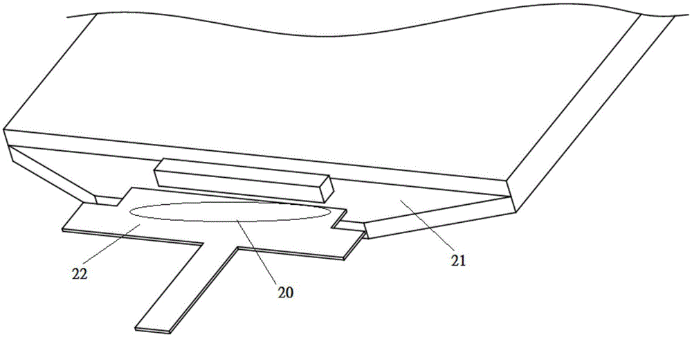
[0016] Please refer to figure 2 and image 3 , figure 2 is a schematic diagram of the oblique cutting of the existing thin film transistor, image 3 It is a schematic diagram of reusing semi-finished boards according to an embodiment of the present invention. like figure 2 As shown, when the thin film transistor panel is cut irregularly, due to the limited area of ​​the region 20 , the arrangement of the dummy pressure test board (CellTestPad) i...


PUM


Abstract

The invention discloses a cell test method for a fanout area at a liquid crystal or OLED (Organic Light Emitting Diode) display panel step. The method comprises the following steps: when the end length of a semi-finished FOG (FPC (Flexible Printed Circuit) on glass) is greater than a critical value, adding a cell test pad for cell test to the end of the semi-finished pad; placing an alignment mark at the cell test pad; and performing a cell alignment program by using a charge coupled device. When the end length of the semi-finished FOG is smaller than a critical value, signals are transmitted via part of pins of the FPC and conduction of the signals is controlled via a metal oxide semiconductor (MOS) in the cell test.

Description

technical field [0001] The present invention proposes a dummy pressure test method and device, especially a dummy pressure test method and device for liquid crystal or OLED display panels. Background technique [0002] In the manufacturing process of liquid crystal displays, it is necessary to continuously monitor the quality problems of the products. From the monitoring process, unqualified products are screened out in time to ensure accurate production. From the monitoring results, we can understand the problems or risks in the production process. At present, before binding the display driver IC (DisplayDriverIC) and the touch controller IC (TouchControllerIC), it is necessary to perform a dummy pressure test (CellTest) on the panel, and only the panel with a normal display effect will flow to the next stage. Display driver IC (DisplayDriverIntegratedCircuit, DDIC) keying action, after completing the digital diagnostic integrated circuit keying, the overall display effect...

Claims


Application Information

Patent Timeline
Patent Type & Authority Applications(China)
IPC IPC(8): G09G3/00
CPCG09G3/006G09G3/3225G02F1/13458G02F2203/69G09G3/3648G02F1/136254H01L22/32G02F1/133G02F1/1309G02F1/13306G02F1/13338G06F3/0412G01R31/00
Inventor 熊彬王英琪黄俊宏
Owner WUHAN CHINA STAR OPTOELECTRONICS TECH CO LTD
Learn More